Fracture Analysis of Parts - Fracture Analysis Technology
2024-09-21 06:00:59
Fracture analysis is divided into two categories: macro analysis and micro analysis. The magnification is 50× or less called macroscopic fracture analysis, and the magnification is 50× or more is called micro fracture analysis.
First, macro analysis
Macroscopic analysis refers to the observation of fractures with the naked eye, a magnifying glass, or a low-magnification optical microscope. Macroscopic analysis is the basis of fracture analysis. The macroscopic analysis can determine the nature of the fracture, the state of the force, the location of the crack source, the direction of crack propagation and the evaluation of material properties.According to the roughness of the fracture surface and the reflection condition, the fracture property can be roughly judged. The general cleavage fracture surface is smooth and flat, and the fracture color is bright and metallic. The surface of the fracture of the dimple is rough and uneven, and the surface color is gray and the crystal particles have no metallic luster. There are usually beach-like patterns on the fatigue fracture, and the fatigue source is smooth and delicate. The brittle material instantaneous break zone is crystalline, and the ductile material is fibrous and shear lip fracture. The brittleness along the crystal fracture is a crystal facet and a reflective facet. The stress corrosion fracture surface has no metallic luster.Observing the plastic deformation, shearing lips, burrs and steps on the fracture can judge the force of the parts. The brittle fracture has no signs of macroplastic deformation near the fracture. There is no shear lip at the edge of the fracture source, and the fracture is perpendicular to the normal stress. There is obvious plastic deformation near the shear fracture, the fracture is inclined at an angle of 45°, and the fracture extends along the plane of maximum shear stress.For the crack source and crack propagation direction, see "Determination of the location of the crack source" and "Interception, cleaning and preservation of the fracture sample".Material performance evaluation: The material properties can be roughly estimated based on the proportion of the fiber zone, the radiation zone and the shear lip on the tensile fracture. The plasticity toughness of the material with a large proportion of the fiber area is good, and the plasticity of the material with a large proportion of the radiation area is reduced, and the brittleness is increased. Another example is that if there is no radiation zone on the impact fracture, the plasticity of the material is good. If the proportion of the radiation area is large, the material is brittle.In addition, it is necessary to observe whether there is oxidation color on the surface of the fracture surface and whether there is trace of corrosion, and judge the working temperature and working environment of the part.Second, the optical microscope fracture analysis
Optical microscopy fracture analysis refers to the analysis of fractures using a stereo microscope with a metallographic microscope and a double barrel.After macroscopic analysis, the microstructure and shape of the crack, the orientation of the crack and the initial end of the crack, the microhardness change on both sides of the crack, the distribution of the inclusions and the oxide or corrosion product morphology in the crack were observed.In order to find out the relationship between the direction of the fracture and the tissue, the microstructure corresponding to the fracture is often observed under an optical microscope. After the fracture is protected, a full-phase sample is prepared on a section perpendicular to or at an angle.The fracture replica can also be observed with an optical microscope.Third, the electron mirror fracture analysis
Transmission electron microscopy and scanning electron microscopy have been widely used in fractures in recent years.The application of transmission electron microscopy in fracture analysis is mainly:(1) The plastic-carbon secondary replica is used to observe the fracture morphology, which gives details that cannot be resolved by scanning electron microscopy and can be observed at higher magnifications. For example, under the scanning electron microscope, it is difficult to observe the fatigue fringes in the steel. For example, a plastic-carbon secondary replica can be observed under a transmission electron microscope to obtain a clear fringe image. Figure 2-11 is a photo of a plastic double carbon replica of the fatigue fracture of the 18NCl6 steel tail output bevel gear. Fatigue streaks were not observed under the S-570 scanning electron microscope.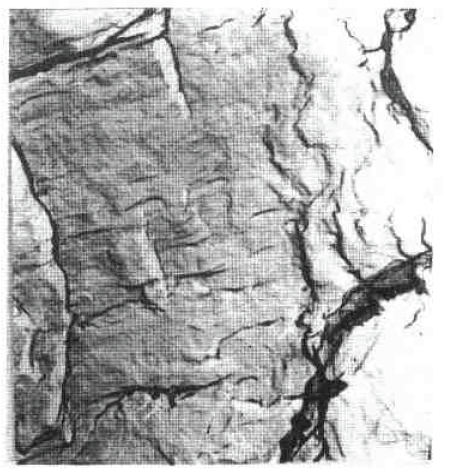 Figure 2-11 18NC16 steel cone tooth loss fatigue pattern × 28000(2) Fracture extraction complex: Extract the inclusions on the fracture or the second phase by using Ac paper to determine the crystal structure of these particles by electron diffraction analysis. For example, the particle composition given by the energy spectrum analysis can be more accurate. Structure. Figure 2-12 shows the strip a-Mns inclusions on the fracture of 35CrNiMoV steel and its electron diffraction spectrum.
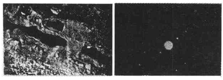 (a) fracture (b) diffraction
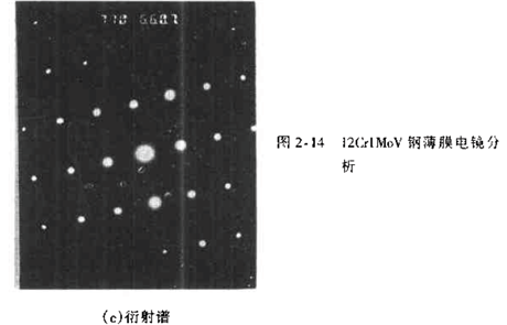
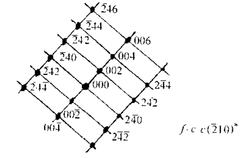 (c) IndicatorFigure 2-12 Inclusions on the fracture of 35CrNiMoV steel(3) In order to find out the cause of the fracture, it is sometimes necessary to cut the metal film from the fracture for transmission electron microscopy analysis. Study the shape, size and distribution of the fractures causing the fracture and the orientation relationship with the mother. Figure 2-13 shows the cleavage fracture of 12CrlMoV steel, and Figure 2-14 shows the transmission electron micrograph and diffraction spectrum of the metal film cut from the fracture. The reason for the cleavage fracture produced by the analysis is due to the precipitation of the nitride of the flaky vanadium on the (001) plane.
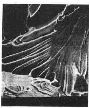 Figure 2-13 12CrlM0v steel cleavage fracture
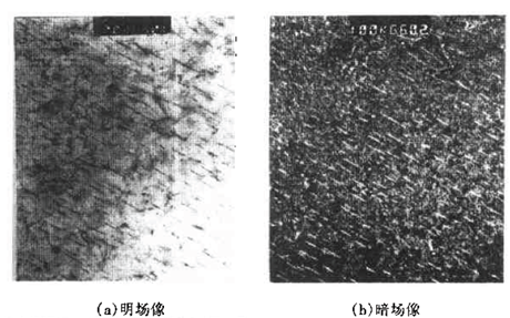
 The scanning electron microscope is widely adjustable in the fracture analysis because the magnification is continuously adjustable (from 20 times to 10,000 times), the depth of field is large, and the stereoscopic effect is strong, and no additional sample is needed.(1) Scanning electron microscopy was used to observe the fracture morphology.(2) Observing the cross-sectional structure at a certain angle from the fracture, and studying the correspondence between fracture morphology and microstructure, crack orientation and fracture mechanism. Figure 2-15 (a, b) is a photograph of the fracture profile of a duplex steel. It is seen from photograph 2-15(a) that at higher ΔK, cleavage fracture mainly occurs in the ferrite phase. At low ΔK and high ΔK (Fig. 2-15b), the fatigue crack bypasses the martensite and always spreads within the ferrite phase.
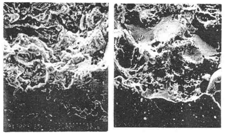 (a) (b)Figure 2-15 Duplex steel fracture profile(3) Scanning electron microscopy with energy spectrum or spectrum can be used to analyze the inclusions, second phase or micro-regions on the fracture.(4) On the scanning electron microscope equipped with dynamic stretching table, the whole process of crack initiation, expansion and fracture of the tensile sample can be observed.(5) Using the same corrosion reagent as the metallographic etchant to shallowly corrode the fracture surface, the fracture morphology and microstructure can be simultaneously displayed.(6) Using the positional etch pit technique to study the crystal orientation and analyze the fracture mechanism or fracture process by using the relationship between the geometry of the crystal material after etching and the crystal plane index. Table 2-3 shows the corrosive agents commonly used in corrosion pit technology. The etching time is generally from a few seconds to a dozen seconds.(7) Quantitative analysis of fractures to study the relationship between the distribution, size and quantity of several topographic features on the fracture.(8) The feature of stereoscopic appearance can be observed by the SEM stereoscopic technique. Figure 2-16 shows a stereoscopic photo of a low carbon steel.Table 2-3 Corrosion agents commonly used in corrosion pit technology
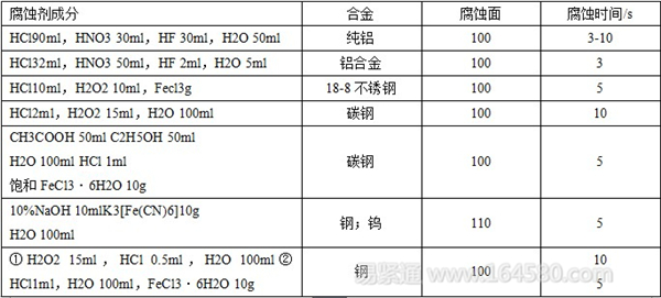
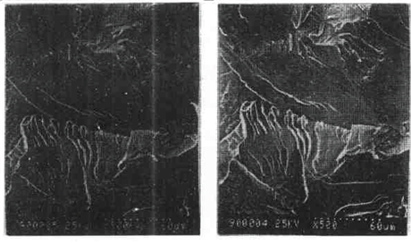 (a) (b)Figure 2-16 Low carbon steel stereo pair
Off-Grid Solar System,Solar Energy System,Solar Solution Off-Grid
China Searun Solar Solution Co., Ltd. , https://www.searunsolar.com