Typical plastic mold design diagram 3 cases
Since the beginning of the 21st century, with the development of modern industry, plastic products have become more and more widely used in various fields such as industry, agriculture, construction, transportation, sports and daily life. Plastics is the fourth largest industrial material emerging in the modern era after steel, wood and cement. The key to the production of plastic products is often the mold. The plastic mold industry accounts for an increasing proportion of modern manufacturing. The level of mold technology directly affects the quality, cost and speed of industrial products, and the level of mold technology is ultimately reflected in the design of mold structure.
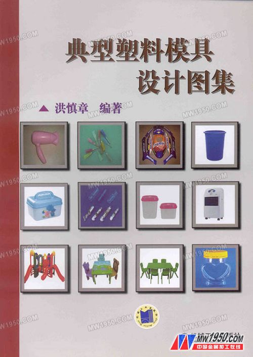
The "Typical Plastic Mold Design Atlas" collated and collected 260 typical plastic mold design legends. The contents include: 108 injection molding mold design legends, 64 compression molding mold design legends, 74 extrusion molding head design legends, and 14 hollow blow molding mold design legends. Each illustration includes a mold structure design drawing, a plastic parts drawing, selected materials, and textual descriptions to help the reader understand the main structural composition and working principle of the mold.
The "Atlas of Typical Plastic Mould Design" was published by the Machinery Industry Press.
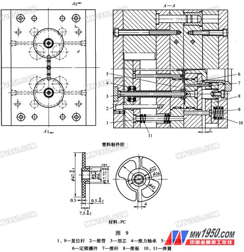
9. Spiral gear injection mold (Figure 9)

Description:
1) The mold adopts a typical spiral push-out structure and is in the form of a two-cavity.
2) The workpiece is a left-hand helical gear with a helix angle of 7°; the φ47 flange connected to it has a width of only 4 mm at the joint and only 2 mm at the thinnest part of the flange. Prone to deformation and damage. In order to facilitate the introduction of the helical gear, the main body part of the gear and the flange are respectively formed in the movable plate and the fixed plate, and at the same time, in order to prevent the flange of the workpiece from being damaged during the mold opening and the workpiece to be left in the movable mold, a fixed mold is introduced. mechanism.
3) After injection molding, under the action of the spring 10, the push rod 7 pushes the flange of the workpiece away from the fixed mold insert 6 and remains on the side of the movable mold. At the time of introduction, since the thrust bearing 4 is provided at the tail of the push 2, the push tube 2 is spirally ejected in the spiral direction of the gear to release the workpiece from the movable mold insert 5.
4) When clamping, the push rod 7 and the push tube 2 are respectively reset by the reset levers 1, 9.
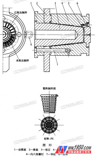
33. Waste paper injection mold (Figure 33)

Description:
1) The mold adopts a push-plate release structure, which is in the form of a cavity and a cavity.
2) The mold structure is suitable for forming a mesh. The circular groove is machined in the cavity of the fixed template 4, and care should be taken not to affect the extraction, and the groove of the core 3 is processed in the direction of the mold release direction.
3) Since the core and the cavity are all identical except for the molding groove, the length of the guide post 7 can be lower than that of the core, and mainly serves as a guiding effect on the push plate 2.
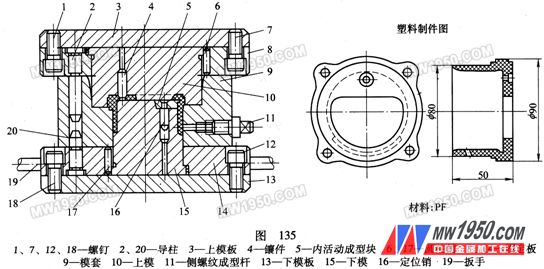
135. Instrument holder compression mold (Figure 135)

Description:
1) The mold is a semi-closed pressing mold with a side thread forming rod 11 in the form of a one-die structure. The position pin 16 is fixed at one end to the inner movable forming block 5, and the other end is in clearance fit with the lower mold 15.
2) After press forming, the side thread forming rod 11 is unscrewed by a special wrench, and the upper and lower molds 10, 15 are unloaded in the outer mold removing frame, and the parts are left in the mold sleeve 9, and the parts are taken out, and then the activities are taken out. The forming block 5, that is, the obtained piece.
The above content is selected from the "Special Plastic Mold Design Atlas" published by Machinery Industry Press.

Author: Hong Shen Zhang, eds.
Book number: 978-7-111-25817-9
Book price: 40.00 yuan (including postage)
Book content consultation telephone-88379405
Book purchase phone ~98-709 娄 teacher
Post office remittance:
Address: "Metal Processing" magazine, No. 22, Mianzhuang Street, Xicheng District, Beijing, China Postcode: 100037
Call to 709
Fax Email:
Bank transfer:
Bank: Bank of China Industrial and Commercial Bank Million Village Branch Account Name: Machinery Industry Information Research Institute Contact: Yan Pingzheng Wang Lei (in the postscript column, must indicate the "metal processing" magazine book)
Synchronizer Ring for ISUZU Dmax, Gear Ring for ISUZU Dmax, Synchronizer Assebmly for Pick Up, Isuzu Dmax Brass Ring
ShaoXing Change Auto Synchronizer Ring Co.,Ltd , https://www.sxcjautoparts.com