The application of ThinkDesign technology in innovative design (2)
2. Unified environment for parts and assembly
Designers who have used 3D CAD software are well aware that the parts model and the assembly model files are separate, with different extension names, and each time they need to move the assembly model file, its child parts and part model files must be moved together; Or you must re-adjust the file path relationship of the assembly, which does bring inconvenience to the design work.
All model files of ThinkDesign software use the same extension name (.e3); due to the need to take into account parametric CAD technology, the extension file name (.e2) is used for the drawing file. In this way, the parts and assembly files are unified and independent of each other, and the model file is processed by the impeller to explain how to solve the above problems.
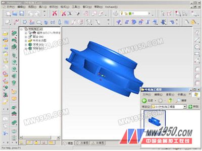
First, drag the impeller machining model into the software modeling environment in the catalog. From the lower right corner of the left graph in Figure 4, it can be seen that the open model file is the part model, but it is the assembly model, because in actual production. The designer needs to modify the blades in the impeller machining model; the manufacturer only needs the modified impeller machining model file.


Figure 4
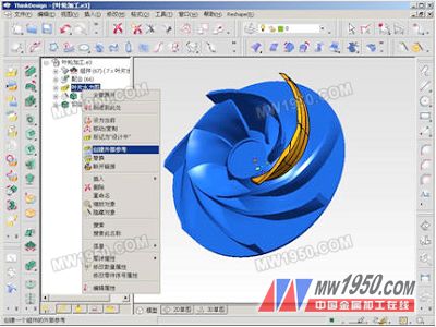
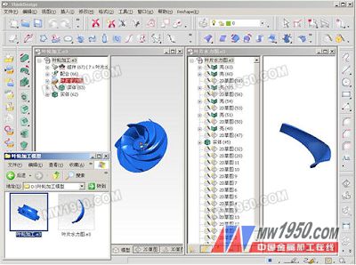
To achieve this idea, use the menu command shown on the right side of Figure 4, select "Create External Reference" to turn the blade hydraulic map feature into an external model file. At this time, add a file name in the directory (see Figure 5, bottom left). The corner shows). If there are more feature structures on the feature tree, you can also set the modified model file to "mark as design" to distinguish between modified and unmodified components, and identify the background as "red" on the feature tree. The result is shown in Figure 5.

Figure 5
Finally, when the design modification is completed and a separate impeller machining model file needs to be formed, the menu command shown in the right diagram of Figure 4 can be used to select the "disconnect link" to cancel the association with the blade hydraulic model file. The modified results are saved in the impeller machining model file, and can be deleted for the blade hydraulic model file.
3.2 Pragmatic free modeling method
Parametric CAD modeling technology has provided designers with the ability to form 3D models from 2D sketches through feature modeling techniques such as rotation, stretching, excision and scanning; from interpolation curves, splines, NURBS curves to lofted surfaces, rotating surfaces, NURBS surfaces, and finally the surface modeling; then the physical features and surface features can be edited, parameter driven, size-related, etc. These are the necessary modeling techniques for parametric CAD software.
In addition to the parametric CAD modeling technology, the modeling technology of ThinkDesign software extends the modeling technology on the basis of the following three points:
Previous page next page
Hexagon mosaic is classic for home decoration, it can brighten up your room, add dramatic fashion to your house. We offer several sizes like 10mm, 15mm,23mm,32mm,48mm and 73mm hexagon, various colors are available. Hexagon glass mosaic can be glossy, matte, iridescent surface, flat or 3D effect. Mosaic can be used in Exterior or Interior Wall Applications, like kitchen wall, backsplashes and bathroom feature walls, bring fashion and style to your home. Hexagon recycled glass mosaic offers a large selection of vibrant colors, appealing finishes and distinct shapes that will make a stylish statement for your house.

Blue Glass Tile,Glass Hexagon Tile,Hexagon Mosaic Tile,Hexagon Glass Mosaic Tile
C&K MOSAIC , https://www.cnkmosaics.com