Start-and-go crank-cutter - simulation while designing (2)
Try to use methods that inherit the join conditions from the assembly environment, which can reduce many unnecessary repetitive tasks. (See Figure 6.) Some readers may encounter a strange phenomenon. Taking a four-bar linkage mechanism as an example, in the original assembly environment, each rod is connected using an insertion constraint, and the model is fully movable without any error. Entering the simulation environment and transforming these insertion constraints one by one, you will find that the first three insertion conditions are smoothly converted into hinges, but after turning to hinged, the software will automatically prompt the addition of conditional degrees of freedom. (See Figure 7)
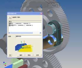
Figure 6 Using constraint inheritance

Figure 7 Adding conditions with redundancy errors
The bottom calculation of the motion simulation module of AIP11 is based entirely on the conceptual formula in the mechanism of the machine. The calculation of the degree of freedom of the link mechanism can refer to the “GRUEBLER theoremâ€, so that the space four-bar linkage has only one mobility M=1 (M= 6(NJ-1)+ΣJ N is the number of rods, J is the number of joints, ΣJ is the sum of joint degrees of freedom), and the number of degrees of freedom of the last joint is calculated to be 4, so the last joint should be modified to “spherical circle†Slot motion".
Similarly, modify the contact point of the connection error in the start-stop crank flying shear mechanism. It is recommended that the software's own “repair redundancy†command (see Figure 8) solve the similar problem. For simpler dynamic models, the problem can be modified directly in the “Repair Redundancy†command menu. For complex dynamic models, only reasonable suggestions can be made here (see Figure 9). You need to use the "Insert Connection" command to redefine the connection.
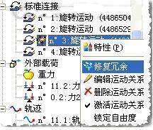
Figure 8 fix connection error
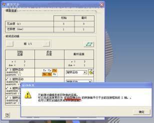
Figure 9 repair interface
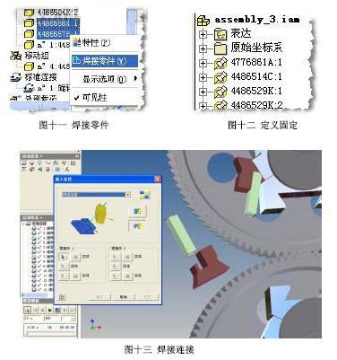
The connection of the main drive gear adopts the "external gear meshing motion", and the conditional addition can be completed by selecting the indexing circle of the two helical gears. (See Figure 10) The physical block and the function of defining the ground can be replaced with the "welded parts" and "fixed" commands. (See Figure 11 and Figure 12) In fact, there is also a "welding connection" condition in the connection condition of AIP11. This is two different concepts from the welding parts just mentioned. The essential difference between the two is that "welding parts" allow Several parts are defined as a whole in motion simulation, but the force cannot be transmitted between these parts. The "welding connection" can achieve the force transmission, but the "welding connection" can only be added in two parts, and several parts can not be collectively defined at the same time. Here we define the crank and the cutting edge of the clipper as a "weld joint" because the force of the crank during the shearing process is calculated. (See Figure 13)
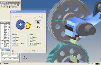
Figure 10 external gear meshing motion
Previous page next page
Led Flexible Rope Light,Led Neon Flex Rope Light,Silicone Led Rope Light,24V Waterproof Rope Light
Tianjin Jinji Optoelectronic Technology Co., Ltd. , https://www.tjjjgd.com