Photovoltaic plant solar tracking system technical requirements (GB/T 29320-2012)
1 Scope
This standard specifies the technical requirements and test methods for the appearance, support structure, drive device, control system, installation, reliability, and environmental adaptability of the solar power plant solar tracking system (hereinafter referred to as the tracking system), as well as inspection rules, signs, and packaging. Technical requirements for transportation and storage.
This standard applies to flat panel and concentrating solar tracking systems for photovoltaic power plants.
2 normative references
The following documents are indispensable for the application of this document. For dated references, only dated versions apply to this document. For undated references, the latest version (including all amendments) applies to this document.
GB/T 191 packaging and storage icon logo
GB/T 2423.1 Environmental testing for electric and electronic products Part 2: Test methods Test A: Low temperature
GB/T 2423.2 Environmental testing for electric and electronic products Part 2: Test methods Test B: High temperature
GB/T 2423.3 Environmental testing for electric and electronic products Part 2: Test methods Test Cab: Constant moisture method
GB/T 2423.21 Environmental testing for electric and electronic products Part 2: Test methods Test M: Low air pressure
GB 4208 enclosure protection class (IP code)
GB 4824 Industrial, Scientific and Medical (ISM) Radio Frequency Equipment Electromagnetic Disturbance Characteristics Limits and Measurement Methods
GB 5237.2 aluminum alloy profile - Part 2: Anodized profile
Cross-cut test of GB/T 9286 paint and varnish paint film
GB/T 13384 general technical conditions for mechanical and electrical product packaging
GB/T 13452.2 Determination of paint and varnish film thickness
GB 13955 residual current operation protection device installation and operation
GB 16895.23 Electrical installations of buildings - Part 6-61: Inspection - First inspection
GB/T 17626.2 Electromagnetic Compatibility Test and Measurement Technology Electrostatic Discharge Immunity Test
GB/T 17626.3 Electromagnetic Compatibility Test and Measurement Technology Radio Frequency Electromagnetic Field Immunity Test
GB/T 17626.4 Electromagnetic Compatibility Test and Measurement Technology Electrical Fast Transient Burst Immunity Test
GB/T 17626.5 Electromagnetic Compatibility Testing and Measurement Technology Surge (Shock) Immunity Test
GB/T 17626.6 Electromagnetic Compatibility Test and Measurement Technology Radiated Field induced Conducted Harassment Immunity
GB/T 17626.8 Electromagnetic Compatibility Testing and Measurement Technology Power Frequency Magnetic Field Immunity Test
GB/T 17626.11 Electromagnetic Compatibility Test and Measurement Technology Voltage Dips, Short Interruptions and Voltage Variations Immunity Test
GB 18802.1 Low Voltage Surge Protector (SPD) Part 1: Surge Protector Performance Requirements and Test Methods for Low Voltage Distribution Systems
GB/T 18802.21 Low-voltage surge protectors - Part 21: Surge protectors (SPDs) for telecommunications and signal networks - Performance requirements and test methods
GB/T 19582.1 Industrial Automation Network Specification Based on Modbus Protocol Part 1: Modbus Application Protocol
General Technical Conditions and Safety Requirements for GB/T 19826 Power Engineering DC Power Supply Equipment
GB/T 20540.6 Measurement and control of digital data communication Field bus for industrial control systems Type 3: PROFIBUS specification Part 6: Application layer protocol specification
GB/T 24343 Test Specification for Insulation Resistance of Electrical Equipment for Industrial Machinery
GB 50009 Building Structure Load Specification
GB 50017 steel structure design specification
GB 50205 steel structure engineering construction quality acceptance specification
DL/T 768.7 Power Fittings Manufacturing Quality Steel Parts Hot Dip Galvanizing
JGJ 82 steel structure high strength bolt connection technical specification
3 Terms and Definitions
The following terms and definitions apply to this document.
3.1
Tracking system
Through the joint action of mechanical, electrical, and electronic circuits and programs, the space angle of the photovoltaic module plane is adjusted, and the device for tracking the incident solar light to increase the power generation of photovoltaic modules is realized. Also known as the tracking system for Japan, chase tracking system, and solar tracker.
Tracking systems can generally be divided into single-axis tracking systems and dual-axis tracking systems. The specific parameters tracked can be divided into a ground coordinate system and an equatorial coordinate system according to the coordinate system.
Tracking system can be divided into independent type and linkage type according to structure type.
The tracking system can be classified into T-type (tower column type, column type), V-type (double V-type, W-type), O-type (disc type) and other types according to the appearance shape.
The tracking system can be classified into general (general) type (flat type solar tracking system) and precision type (concentrated type solar tracking system) according to tracking accuracy. Spot-focus concentrators generally require dual-axis tracking, and line-focus concentrators require only single-axis tracking.
3.2
Flatbed tracking system flat plate tracking system
A tracking system for installing flat panel PV modules.
3.3
Spotlight Tracking System CPV tracking system
A tracking system for installing concentrated photovoltaic modules.
Note: Convergence magnification is less than 100 times for low magnification, and no less than 100 times for high magnification.
3.4
Single-axis tracking system single-axis tracking system
A tracking system that rotates about a one-dimensional axis. Also known as a one-dimensional tracking system.
Note: The single-axis tracking system can be divided into horizontal single-axis tracking system, tilt single-axis tracking system and vertical single-axis tracking system.
3.5
Dual-axis tracking system dual-axis tracking system
A tracking system that rotates about a two-dimensional axis. Also known as two-dimensional tracking system.
Note: The two-axis tracking system uses the ground plane as the reference system, tracking the solar altitude angle and the solar azimuth angle; taking the equatorial plane as the reference system, the declination angle and the hour angle are followed.
3.6
Line focus tracking system line-focus tracking system
Photovoltaic concentrators use a lens or mirror to focus sunlight on a tracking system on a photovoltaic array line array.
3.7
Point-focus tracking system
Photovoltaic concentrators use a lens or mirror to focus sunlight on a point-by-point tracking system on a photovoltaic module.
3.8
Solar incidence angle of incidence
The angle between the sun ray and the normal to the receiving plane.
3.9
Solar azimuth angle
The projection of the connection between the center of the sun to the ground observation point on the local horizontal plane and the angle between the south (northern hemisphere) or true north (south hemisphere).
3.10
Solar elevation angle
The angle between the sun's rays and the ground plane.
3.11
Declination of solar declination
The angle between the center of the earth and the center of the sun and the equatorial plane (the northern hemisphere is positive).
3.12
Hour angle
The angle between the sun's projection on the equatorial plane and the projection of the sun's projection on the equatorial plane at noon.
3.13
Tracking accuracy
The tracking accuracy of the single-axis tracking system is expressed in terms of the angle between the direction of the human-cast sunlight ray and the normal of the receiving plane in the tracking direction.
The tracking accuracy of the two-axis tracking system is represented by the solar angle.
3.14
Active control of active control
According to the geographic location and local time real-time calculation of the solar radiation angle, through the control system to adjust the PV array to a specified angle, also known as astronomical control or program control.
3.15
Passive control
The sensing device determines the angle of the solar radiation through the sensing device, thereby controlling the rotation of the photovoltaic array and tracking the solar radiation angle, including the light sensing control method and the gravity balance control method.
3.16
Compound control
Active control and passive control combined control.
4 requirements
4.1 General provisions
4.1.1 The technical specifications of the tracking system shall meet the environmental adaptability requirements, electrical safety requirements, appearance requirements, support structure requirements, drive device requirements, control system requirements, and reliability requirements.
4.1.2 The main technical specifications of the tracking system The project shall include the contents of Appendix A.
4.1.3 tracking system model preparation method should comply with the provisions of Appendix B of this standard.
4.2 Environmental Adaptability Requirements
4.2.1 Tracking system wind resistance requirements
The tracking system should be able to operate normally with a wind speed of 18m/s or less, and the wind speed should be increased to 18m/s. The tracking system should automatically enter wind resistance. In the wind-resistant state, the tracking system should be able to withstand a wind speed of 33m/s; in areas above the 12th wind, it should be able to withstand a wind speed of 42m/s.
The tracking system that automatically enters the wind-resistant state without strong winds should be able to withstand the local maximum wind speed in 25 years.
4.2.2 tracking system anti-snow requirements
In snowy areas, the tracker system should have manual or automatic snow avoidance.
4.2.3 tracking system resistance to high and low temperature requirements
4.2.3.1 The operating environment temperature of the tracking system should be -25°C to 70°C
4.2.3.2 The tracking system storage temperature range should be -40 °C -70 °C
4.2.4 tracking system heat and humidity requirements
The tracking system should be able to adapt to a working environment with a maximum relative humidity of 85% when the ambient temperature is 40°C.
4.2.5 Tracking System Work Atmospheric Pressure Requirements
In areas below 3000m in altitude, the tracking system should be able to adapt to the atmospheric pressure of 70kPa-106kPa; in areas above 3000m above sea level, the tracking system should be able to adapt to the atmospheric pressure of 40kPa-70kPa.
4.2.6 Tracking System Electrical Protection Level Requirements
The electrical enclosure of the tracking system should have an IP 54 degree of protection.
4.2.7 Anti-corrosion requirements for metal surfaces of tracking systems
4.2.7.1 Corrosion protection of steel components Galvanizing, anti-corrosion coating and other anti-corrosion measures shall be used to ensure the shelf life is more than 25 years.
4.2.7.2 Hot-dip galvanizing is adopted for galvanized steel parts, and the minimum average thickness of galvanized parts for hot dip galvanized steel parts is not to be less than 65 μm. The appearance, adhesion strength and uniformity of the galvanized layer are to comply with DL/T 768.7. Provisions.
4.2.7.3 Anticorrosive coatings The anticorrosive coating of steel parts shall be in accordance with the provisions of GB 50205 in terms of thickness, appearance and adhesion.
4.2.7.4 Anti-corrosion of aluminum alloy parts may be anodized and shall comply with the provisions of GB 5237.2.
The film thickness of the oxide film should not be less than AA15, and AA20, AA25 should be used for the environment where the atmospheric pollution conditions are harsh or the film thickness of the oxide film needs to be hardened. The average thickness of the anodized film and the local film thickness should meet the requirements of Table 1. .

When the aluminum alloy material is contacted and fastened with other metal materials other than stainless steel or with acidic or alkaline non-metallic materials, a barrier material should be used to prevent direct contact with it.
4.3 Lightning Protection and Grounding Requirements
4.3.1 Tracking system power and signal ports shall adopt lightning surge protection measures.
4.3.2 Tracking system Power port The surge protector performance requirements should comply with the provisions of GB 18802.1. Surge protector combination wave (1.2/50μs-8/20μs) impact test open circuit voltage should not be less than 4kV. Pressure limiting surge protectors should have separate devices and remote contacts.
4.3.3 Surge Protector Performance Requirements for Tracking System Signal Ports The requirements of GB/T 18802.21 shall be met. Signal surge protector transmission rate, insertion loss and other parameters should meet the requirements of the normal operation of control and communication lines.
4.3.4 Tracking system Power supply lines and metal core control and communication lines shall be shielded. The line shield or shield metal tube should be equipotential bonding and grounded.
4.3.5 The tracking system uses non-metallic enclosures and electrical control cabinets, boxes, etc. shall be shielded.
4.3.6 The electric control cabinet and box of the tracking system should be set with equipotential grounding terminal board and connected with the grounding device of the photovoltaic power station, surge protector grounding wire, safety ground wire, shield of electric cabinet or control box, metal shell, etc. Should be reliably connected with the terminal board. Surge protector connection wires should be short straight.
4.3.7 Tracking system The metal parts should be equipotential bonding and grounded. Tracking system base metal structures or steel bars shall be connected to the grounding device of the photovoltaic power plant to form a common grounding system.
4.3.8 When using the centralized control method, the tracking system electrical control cabinet shall adopt direct lightning protection measures.
4.3.9. The grounding resistance of lightning protection should not be greater than 100, and the grounding resistance of the common grounding device should also meet the safety requirements of 4.4 on electrical equipment.
4.4 Electrical Safety Requirements
4.4.1 Tracking System Protection Grounding Requirements
4.4.1.1 track the motor, transformer base and shell, control cable sheath, terminal box metal shell should be grounded, any grounding point of the ground resistance does not exceed 40.
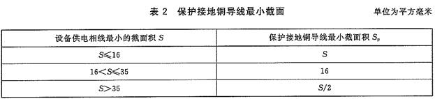
4.4.1.2 The tracking system cannot be used to constitute a rotating part of the equipotential bonding using a soft copper wire connection. Copper conductor minimum section shown in Table 2.
4.4.2 Tracking System Media Strength Requirements
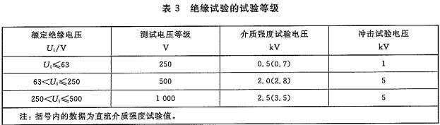
Between each independent circuit and ground (ie, metal frame), it should be able to withstand the frequency of 50Hz ± 5Hz power frequency dielectric strength test, which lasted 1min (can also be equivalent DC voltage), and there should be no breakdown or flashover. The test grade of the insulation test is shown in Table 3.
4.4.3 tracking system electrical equipment leakage protection requirements
Tracking system leakage protection requirements shall comply with the provisions of GB 13955.
4.4.4 Tracking System Insulation Resistance Requirements
When the tracking system is installed with a leakage protection device, the insulation resistance between each independent circuit and ground (ie metal frame) shall not be less than 0.5MΩ at 500V DC voltage; when the tracking system is not equipped with a leakage protection device, at 500V DC voltage, each The insulation resistance between the independent circuit and ground (ie metal frame) should not be less than 1MΩ.
4.5 tracking range
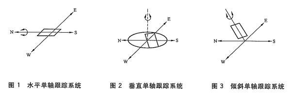
4.5.1 horizontal single-axis tracking system shown in Figure 1, the tracking range should not be less than ± 45 °; vertical single-axis tracking system shown in Figure 2, the tracking range should not be less than ± 100 °; tilt single-axis tracking system shown in Figure 3, tracking range Should not be less than ±45°.
4.5.2 Two-axis tracking system, the range of azimuth angle should be ±100°, the range of height angle should be 10° to 90°, the range of declination angle should be ±23.45°, and the range of time angle should be ±100°.
4.6 tracking accuracy
4.6.1 The tracking accuracy of the flat-plate single-axis tracking system is ±5°.
4.6.2 Line Focus Tracking System Tracking accuracy is ±1°.
The tracking accuracy of the 4.6.3 flatbed dual-axis tracking system is ±2°.
The tracking accuracy of the 4.6.4 point tracking system is ±0.5°.
4.7 energy requirements
The average daily energy consumption of the tracking system should not exceed 3% of the power generated by the photovoltaic power generation system.
4.8 Reliability Requirements
The service life of the tracking system under normal maintenance conditions should be 25 years and the availability rate should not be less than 95%.
Note: The service life refers to the life cycle of the tracking system under normal maintenance.
4.9 Appearance requirements
4.9.1 Basic Requirements for Tracking System Appearance
The body surface is free of scratches, cracks, deformations, and damages. The surface coating should be free from peeling, the parts should be firmly connected, the metal part should be free from corrosion, and the mark should be clear and correct.
4.9.2 Tracking System Steel Structure Appearance Requirements
4.9.2.1 Welding Appearance Requirements
4.9.2.1.1 The appearance of welding shall meet the relevant requirements in GB 50205.
4.9.2.1.2 The feel of the weld should be uniform and well formed, the transition between the weld bead and the weld bead, the weld bead and the basic metal should be smooth, the welding slag and spatter should be clean, no cracks, slag inclusions, pores, Not filled with other defects.
4.9.2.2 Hot Dip Zinc Appearance Requirements
4.9.2.2.1 Hot dip galvanizing shall be continuous and as uniform and smooth as possible. There may be a dark gray iron-zinc alloy, and there should be no acid bleed out of the zinc layer.
4.9.2.2.2 There may be spotted zinc spots with a diameter of less than 0.5 mm on the local surface.
4.9.2.2.3 Hot dip galvanized surfaces should not have concentrated zinc-free areas, haloes, and corrugations. The total area of ​​scattered zinc-free areas, lobes, and corrugations for general parts shall not exceed the approximate value of 0.500 for the total area of ​​the plating parts; for large parts (such as columns, beams, or parts with a surface area exceeding 2×105 mm2), the total number of plating parts shall not exceed Approximate 0.1% of the area.
4.9.2.3 Surface Coating Requirements
4.9.2.3.1 The surface painting of components shall comply with the provisions in GB 50205.
The surface of the component should not be miscoated or missing, and the coating should not be peeled off and return rust. The coating should be uniform, without obvious 4.9.2.3.2 wrinkle skin, pinholes and bubbles.
4.9.2.3.3 After painting, the marks, marks and numbers of the components shall be clear and complete.
4.9.2.4 Bolt Connection Requirements
4.9.2.4.1 The fastening shall be firm and reliable when the bolts are connected. The exposed threads shall not be less than 2 buckles.
4.9.2.4.2 High-strength bolt connections shall comply with the provisions of JGJ 82.
4.9.3 Tracking System Electrical Appearance Requirements
4.9.3.1 Tracking system The controller box has no sharp corners, there is no obvious scratch on the surface of the box, and there should be a safety mark in the corresponding position.
4.9.3.2 The connection lines of electrical equipment are reasonable and aesthetically pleasing. The outside of bare wires should be protected by means of plastic pipes and other measures.
4.10 Support Structure Requirements
4.10.1 The carbon steel shall be adopted for the support structure. The selection of carbon structural steel shall comply with the provisions of GB 50017.
4.10.2 Strength Requirements for the Support Structure
The strength of steel frame supports shall comply with the provisions of GB 50017.
4.10.3 Stiffness Requirements of Bracket Structure
4.10.3.1 Under the action of the load, the displacement of the top of the support should not exceed 1/60 of the height of the column.
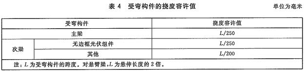
4.10.3.2 Flexural members deflection should not exceed the allowable value of Table 4.
4.10.4 Support Structure Stability Requirements
In wind resistance, snow resistance and working conditions, the support structure should be stable and reliable.
4.10.5 Bracket Structure Hard limit should be set at the design limit position.
4.11 Drive Requirements
4.11.1 The drive should have a self-locking function.
4.11.2 The drive device should be easy to maintain and easy to replace.
4.11.3 Power Plant Requirements
4.11.3.1 Tracking system The power plant shall meet the power needed to enter the protection posture.
4.11.3.2 The power plant may use AC motors or DC motors.
4.11.3.3 The power plant performance (usually including the rated input voltage or current, rated output torque, speed, working voltage or current range, insulation resistance, etc.) shall meet the design requirements and the nameplate shall indicate the main parameters.
4.11.3.4 The power plant should have a backup power source.
4.11.4 Transmission Requirements
4.11.4.1 The mechanical properties of the transmission (generally including gear ratio, rated input and output torque, maximum output torque, mechanical efficiency, holding torque, maximum axial and radial loads, etc.) shall meet the design requirements.
4.11.4.2 The transmission shall be operated smoothly, flexibly, without any stagnation, without abnormal vibration and without noise; there shall be no loosening of connecting parts and fasteners, and there shall be no leakage or leakage of the seals.
4.11.4.3 The transmission sealing parts shall meet the dustproof requirements.
4.12 Control System Requirements
4.12.1 Control Mode
4.12.1.1 The tracking system controls can be divided into three types: active control, passive control and compound control.
4.12.1.2 The control system shall achieve full automatic tracking control within the effective sunshine hours.
4.12.2 Communication Requirements
4.12.2.1 The tracking system and the PV system control system should be compatible.
4.12.2.2 The control system should have the function of uploading data. The data should include the tracking system's real-time running angle, real-time running status, running time, automatic/manual status and anti-wind and snow status.
4.12.2.3 The control system should have a power-off protection function, save the data after power failure is not lost, the control system clock should be able to continue to work for more than 1 week. The operating data should be saved by the control system itself or uploaded for more than 1 year.
4.12.3 Control Protection Requirements
4.12.3.1 The control system should have motor overcurrent protection.
4.12.3.2 The control system shall have a limit function.
4.12.3.3 The control system should have manual functions.
4.12.4 Reset Requirements
4.12.4.1 After the control system is lost/restored, the tracking system should be able to automatically enter the working state to track the sun's trajectory in real time.
4.12.4.2 The control system should have an automatic reset function. After the end of the tracking, it can automatically return to the initial position after tracking.
4.12.5 Electromagnetic Compatibility Requirements
4.12.5.1 Harassment requirements
The turbulence of the tracking system should comply with the relevant provisions of GB 4824.
4.12.5.2 Immunity requirements
The immunity of the tracking system shall comply with the relevant provisions of GB/T 17626.2, GB/T 17626.3, GB/T 17626.4, GB/T 17626.5, GB/T 17626.6, GB/T 17626.8, and GB/T 17626.11.
4.13 Installation Requirements
4.13.1 The tracking system shall check whether the appearance and protective layer are intact after the arrival of the system; whether the model, specification and material meet the requirements of the design drawings, and whether the accessories, spare parts, product technical documents, installation instructions and installation drawings are complete.
4.13.2 Basic parameters (base coordinate position, elevation of different planes, basic dimensions, horizontal deviation of the plane, deviation of the basic positioning axis, basic bearing capacity, elevation and center distance of embedded anchor bolts, etc.) shall be in accordance with the design Claim.
4.13.3 Installation errors shall meet the design requirements.
4.13.4 During the installation process, the protective measures of the workpiece shall be well done. After the installation is completed, the surface coating shall be repaired.
4.13.5 The tracking system should have reliable grounding measures, and the grounding resistance should meet the design requirements.
4.13.6 The tracking system should be commissioned after installation.
4.13.7 Tracking system The distance between the bottom of the photovoltaic module plane and the ground should not be less than 0.3m.
4.13.8 The spacing of the tracking system shall comply with the design requirements and shall ensure that the array of squares (squares close to the sun) before the 9:00 am to 3:00 pm on the winter solstice will not block the rear array.
4.14 Operation and Maintenance Requirements
4.14.1 The tracking system's mechanical structure, electrical lines, appearance coating, etc. should be regularly checked and maintained.
4.14.2 The tracking system's operating angle, manual control system, and emergency actions shall be regularly checked.
4.14.3 The lubrication system of the tracking system should be regularly inspected and maintained.
4.14.4 Tracing Consumables The system should regularly check for wear and replace it at a proper time.
4.14.5 Prepare emergency response measures in response to possible emergencies in the tracking system.
5 test methods
5.1 General provisions
5.1.1 The test content of the tracking system shall include environmental compliance requirements inspection, electrical safety inspection, appearance requirements inspection, support structure performance test, drive device performance test, control system performance test and reliability requirement inspection.
5.1.2 The test method of the tracking system shall meet the corresponding technical requirements and be tested in accordance with the main technical specifications in Appendix A and the test and test items in Appendix C.
5.2 Environmental Adaptability Requirements Inspection
5.2.1 tracking system wind resistance performance test
The wind resistance test of the tracking system adopts a mechanical load test. Under power-on conditions, loads of components or equivalent components should be tested.
Mechanical load test procedure:
a) Prior to the environmental test, the tracking system shall perform electrical and mechanical measurements and visual inspections in accordance with the test standard atmospheric conditions and record test data;
b) Make a rigid test base structure that allows the tracking system to be freely deflected when loaded;
c) Install the tracking system on the base and install it on the windward side;
d) Calculate the wind pressure value of 18m/s according to the requirements of GB 50009, load the load gradually and uniformly in the horizontal direction for a duration of 1h;
e) Adjust the tracking system to wind resistance;
f) calculate the wind pressure value of 33m/s or 42m/s according to the requirements of GB 50009, load the load gradually and uniformly in the horizontal direction for a duration of 1h;
g) After completion of the test, the tracking system shall perform electrical and mechanical measurements as well as visual inspections in accordance with product standards or technical documents, and meet the operational requirements.
5.2.2 tracking system snow pressure resistance test
In accordance with the requirements of 4.2.2, under power-on conditions, the load of the system-loaded components or equivalent components can be tracked and can be manually or automatically taken into the position of avoiding snow.
5.2.3 tracking system resistance to high and low temperature test
5.2.3.1 Low temperature working test
According to the requirements of 4.2.3.1, using the method specified in GB/T 2423.1, the tracking system is subjected to a low-temperature working test, and the power is operated for 2 hours in a (25±1)°C environment.
5.2.3.2 Low temperature storage test
According to the requirements of 4.2.3.2, using the method specified in GB/T 2423.1, the tracking system was subjected to a low-temperature storage test and placed in a (-40±1)°C environment for 16 hours.
5.2.3.3 High temperature working test
According to the requirements of 4.2.3.1, using the method specified in GB/T 2423.2 "Test Bd", the tracking system is subjected to a high-temperature working test and is operated for 2 hours in a (70±1)°C environment.
5.2.3.4 High temperature storage test
According to the requirements of 4.2.3.2, using the method specified in GB/T 2423.2 "Test Bd", the tracking system was subjected to a high-temperature storage test and placed in a (70 ± 1) °C environment for 16 hours.
5.2.4 tracking system damp heat test
According to the requirements of 4.2.4, using the method specified in GB/T 2423.3 "Test Ca", the tracking system is subjected to a constant damp heat test, and the power is applied in an environment of (40 ± 2) °C and a relative humidity of (85 ± 3)%. Run 12h.
5.2.5 Tracking System Work Atmospheric Pressure Test
In accordance with the requirements of 4.2.5, using the method specified in GB/T 2423.21, the atmospheric pressure test of the tracking system was performed, and the power supply was operated for 2 hours in an environment of 70 kPa or 40 kPa.
5.2.6 tracking system electrical protection class test
In accordance with the requirements of 4.2.6, using the method specified in GB 4208, IP protection tests are conducted on the electrical enclosure of the tracking system.
5.2.7 Trace Metal Surface Corrosion Test Method
5.2.7.1 In accordance with the requirements of 4.2.7.2, the thickness, appearance, adhesion strength, and uniformity of the galvanized layer of hot dip galvanized steel parts are tested by the method specified in DL/T 768.7.
5.2.7.2 In accordance with the requirements of 4.2.7.3, using the method specified in GB/T 13452.2, the thickness of the anti-corrosion coating of steel parts coated with anti-corrosion coatings shall be tested.
5.2.7.3 According to the requirements of 4.2.7.3, using the method specified in GB/T 9286, the adhesion of the anti-corrosion coating is tested.
5.2.7.4 In accordance with the requirements of 4.2.7.4, using the method specified in GB 5237.2, the anodic oxide film on the surface of the aluminum alloy parts is tested.
5.3 Lightning Protection and Grounding Inspection
5.3.1 Surge protection test of electrical control cabinet and box
According to the requirements of 4.3, using the methods specified in GB/T 17626.5, the surge test of the power port and signal port shall be conducted. The test level shall be no less than 4kV (line-to-ground). The equipment shall be intact and the tracking control device shall be able to operate normally. jobs.
5.3.2 Equipotential bonding and grounding inspection
According to the requirements of 4.3, visually connect the surge protector grounding wire, safety protective earth wire, electrical cabinet or control box metal casing to the ground terminal board, track the electrical connectivity between the metal parts of the system, and ground Check whether the terminal board is reserved for terminals connected to the common grounding network. The transition resistance at the connection point should not exceed 0.03Ω.
5.4 Electrical Safety Inspection
5.4.1 Inspection System Protection Grounding Performance Inspection
In accordance with the requirements of 4.4.1, a grounding resistance tester or digital low resistance tester is used to test the grounding resistance of any grounding point of the tracking system.
5.4.2 Tracking System Media Strength Performance Inspection
In accordance with the requirements of 4.4.2, using the method specified in GB/T 19826, the media strength of the tracking system is tested.
5.4.3 Tracking System Electrical Equipment Leakage Protection Performance Inspection
According to the requirements of 4.4.3, using the method specified in GB 13955, the leakage protection performance is tested.
5.4.4 Tracking System Insulation Resistance Performance Test
According to the requirements of 4.4.4, using the method specified in GB/T 24343, the insulation resistance of the tracking system is tested.
5.5 tracking range check
According to the requirements of 4.5, the angle ruler is perpendicular to the rotation axis, so that the center of the angle ruler coincides with the center line of the rotation axis, and the maximum angle range that the rotation part can rotate is inspected to check the tracking range of the tracking system. A horizontal angle meter can also be used to check the tracking range of a horizontal single-axis tracking system.
5.6 Tracking Accuracy Check
The inspection of the tracking accuracy adopts the pinhole method, which should be carried out with the load of components or equivalent components.
According to the requirements of 4.6, an opaque light and light plane with a pinhole is fixed parallel to the plane of the assembly. There is a certain distance between the two planes. Run the tracking system in the effective sunlight time to check the deviation of the solar flare on the plane of the assembly. The hole angle checks the tracking system's tracking accuracy.
5.7 Energy Consumption Inspection
According to the requirements of 4.7, the daily energy consumption of the tracking system under normal working conditions was measured by using a watt-hour meter, and the average daily energy consumption of the tracking system was compared with the calculated value of the daily average power generation amount under the standard lighting conditions.
Note: The average daily power generation of the tracking system is based on the daily working hours of 4 hours.
5.8 Appearance Inspection
According to the requirements of 4.9, visual inspection of the tracking system was performed.
5.9 Test of the structural performance of the bracket
5.9.1 In accordance with the requirements of 4.10.1, use the method specified in GB 50205 to inspect the stent material.
5.9.2 In accordance with the requirements of 4.10.2, the test method of 5.2.1 or 5.2.2 shall be used to test the strength of the support structure.
5.9.3 In accordance with the requirements of 4.10.3, use the test methods of 5.2.1 or 5.2.2 to test the stiffness of the support structure.
5.9.4 Test the stability of the bracket according to the requirements of 4.10.4 using the test method of 5.2.1 or 5.2.2.
5.9.5 In accordance with the requirements of 4.10.5, visual inspection is used to check whether the bracket is set to hard limit.
5.10 Drive Performance Test
5.10.1 Perform the self-locking function test on the drive according to the requirements of 4.11.1.
5.10.2 In accordance with the requirements of 4.11.4, under no-load conditions, the drive unit is running continuously and continuously for lh-2h and the transmission is tested for no-load.
5.10.3 In accordance with the requirements of 4.11.4, under rated load conditions, the drive shall meet the design requirements for normal operation and perform load tests on the drive.
5.11 Control System Performance Test
5.11. Flight Control Mode Check
According to the requirements of 4.12.1, check the control method of the tracking system.
5.11.2 Communication Performance Test
5.11.2.1 Test the communication performance in accordance with the requirements of 4.12.2.
5.11.2.2 In accordance with the requirements of 4.12.2.1, the control system is powered off after 7 days, the clock of the control system works normally, and the test of the power off protection performance of the control system is performed.
5.11.3 Protection Performance Test
5.11.3.1 According to the requirements of 4.12.3.2, using the method specified in GB 16895.23, the control system over-current protection performance test. Corresponding technical requirements are partially revised.
5.11.3.2 In accordance with the requirements of 4.12.5, when the control system is in normal operation, the limit switch is manually triggered to test the limit function of the control system.
5.11.3.3 In accordance with the requirements of 4.12.6, manually operate the tracking system in all directions of operation and stop, and test the manual function of the control system.
5.11.4 Reset performance test
5.11.4.1 In accordance with the requirements of 4.12.4.1, in the normal operation of the control system, the power is restored after a power cut of 2 hours, and the reset performance of the tracking position after loss/restore of the control power source is tested.
5.11.4.2 In accordance with the requirements of 4.12.4.2, the control system automatically returns to the initial tracking position after the set time, and automatically changes the real-time tracking data to the initial position data, automatically resets the tracking system and automatically corrects the data. experimenting.
5.11.5 Electromagnetic Compatibility Test
5.11.5.1 Harassment test
According to the requirements of 4.12.5.1, using the method stipulated in GB 4824, harassing test on the tracking system. In the test process, the tracking system should be in the working mode that meets the normal use to maximize the launch.
5.11.5.2 Immunity test
According to the requirements of 4.12.5.2, the tracking system shall be tested for immunity using the methods specified in the relevant basic standards of this requirement. During the test, the tracking system shall be in a working mode that meets the maximum sensitivity of normal use.
6 inspection rules
6.1 type test
6.1.1 When one of the following situations occurs, a type test should be conducted:
―When the new product is finalized and identified;
―The product structure, materials, and processes have undergone major changes that may affect their performance;
― The production should be suspended for more than half a year, and when the production is resumed or during normal production, type inspections should be carried out periodically after periodic or cumulative production.
6.1.2 Type Test Project
For type test items, see Table C.1 in Appendix C.
6.1.3 Sampling of Type Tests
Send two samples and choose one test.
6.1.4 Conformity assessment
6.1.4.1 Classification of defects
The main defects of the tracking system are the safety test items, items that can be eliminated after the replacement of important parts, and defects that cannot be repaired under normal circumstances; the remaining defects are general defects. If the number of general defects exceeds 20% of the total number of inspection items, it is the main defect.
6.1.4.2 Qualification of type test
The conformity criteria for type testing are as follows:
In the type test, if a major defect is found, it is judged to be unacceptable.
―If a general defect is found, a second sampling shall be carried out. The quantity of the second sampling shall be doubled and a second test shall be conducted for the corresponding non-conforming item. If no defect is found, it is judged as passing. If the defect is still found after the second sample has been tested, it is judged as unacceptable.
6.2 factory test
6.2.1 The tracking system is qualified after the factory test and issued by the company's quality management department before it can leave the factory.
6.2.2 The factory test items are shown in Table C.1 of Appendix C.
6.2.3 In the factory test, repair or replacement of unqualified items is allowed until it is qualified.
7 signs, packaging, transportation and storage
7.1 nameplate mark
The tracking system shall be equipped with a nameplate at an appropriate location. The nameplate shall be clear and durable. The content shall include:
―Manufacturer's trademark and name;
―Tracking system name and model number;
― Manufacturing year, month and factory number;
-Product performance standards.
The nameplate mark should meet the relevant requirements of GB/T 191.
7.2 Packaging
7.2.1 The packing box shall meet the relevant requirements of GB/T 13384.
7.2.2 Packaging Marks
There is a tracking system for packing boxes. Text and logos on the packing box should withstand wind, sun, and rain. The contents include:
―Manufacturer's trademark and name;
―Tracking system name and model number;
-Production Date;
― Net quality, total quality;
―Crate outline dimensions (length x width x height);
"Storage and transportation instructions.
7.2.3 There is a packing box tracking system. The packing box should be clean and dry. The tracking system should not be loosened, bumped or turned in the packing box. Shock-sensitive parts should be packed in packing boxes with shockproof material.
7.3 packing files
The tracking system should have the following accompanying factory attachment documents:
-Packing List;
-Product certification;
-user's Guide;
- Warranty booklet (or warranty).
The above packing documents shall be packed in the moisture-proof bag with the tracking system installed in the packing box, and then placed in the packing box.
7.4 Transport and Storage
7.4.1 The tracking system should be placed in the direction specified by the sign to prevent strong vibrations, impacts and collisions during transportation.
7.4.2 The product should be stored in a ventilated, dry environment. The relative humidity during storage should be less than 85%.
Henan liangjin tools co.,Ltd is located in Shangqiu City, Henan Province. The site area of the economic and Technological Development Zone covers an area of more than 30000 square meters, a construction area of more than 3000 square meters, a greening area accounting for more than 30% of the total area, and a design annual production capacity of 30 million rolls of paper, With 10 million screwdrivers, 6 million wrenches, 3 million art knives and 100000 sets of combined tools,specialize in the production of steel tape,tape screwdrivers,art knives,measuring tools,fine tape types of three meters,five meters,seven meters ,five meters,ten meters,as well as double-sided printing tape matte sanding,bright tape.
Steel Tape,Metal Tape Measure,Retractable Tape Measure,Clothing Measuring Tape
Henan Liangjin Tools Co.,Ltd , https://www.liangjintools.com