Overall design of mobile CNC milling machine
The mobile CNC gantry milling machine described herein refers to a gantry milling machine for longitudinal movement of the gantry frame. The biggest advantages of mobile gantry milling machines are: (1) The machine footprint is small. Worktable mobile gantry milling machine, the length of the whole machine must be twice the length of the longitudinal stroke, and the length of the whole machine of the mobile gantry milling machine only needs the longitudinal stroke plus the side width of the gantry. (2) The dynamic response of the machine tool is good. The mobile gantry milling machine adopts a fixed worktable, which is generally cast integrally with the bed. The driving torque of the longitudinal movement of the gantry frame is constant, and will not change due to the change of the load weight of the workpiece, thus ensuring the machining accuracy and the machine tool. Response performance.
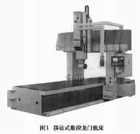
The mobile CNC gantry milling machine (Fig. 1) designed by the author has been put into production as a special machine. It can meet the multi-step machining of large castings and steel parts, such as boring, milling and drilling. It can also be used with right angle milling heads. The four sides are machined. Due to the correct design idea and the quality of the supporting parts, the various indexes of the machine tool have met the requirements of the relevant national standards for CNC portal milling machines. The main design parameters of the portal milling machine are as follows: the working table area is 1800mm × 4000mm, the X-axis stroke is 4000mm, the Y-axis stroke is 2000mm, the Z-axis stroke is 750mm, the spindle power is 18.5kW, and the rapid feed of each axis is 10m/min.
First, the mechanical part design
The whole machine is divided into bed body, gantry frame, sliding table, headstock box, mechanical part of three-axis feed drive mechanism and related CNC servo part. The key points in the design process are as follows.
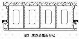
The bed is the basis of this design work. The size design of the bed affects the design of the whole machine, and the rationality of the design directly affects the rigidity of the whole machine. The cross-sectional shape of the bed is a dome shape (Fig. 2). The upper surface of the bed, that is, the work surface, is designed with 9 T-shaped grooves. The groove is completely penetrated for the convenience of the work surface of the bed and the #-shaped groove. The left and right legs of the bed are each designed with a long and narrow plane for placing the rolling linear guide pair. The author designed the rail surface on the two lower sides of the bed, mainly considering the direction of force transmission and unloading. Because the bed will be subjected to the gravity of the gantry frame, the cutting force and the gravity of the workpiece, this design allows the gravity of the gantry frame to be directly transmitted to the foundation of the machine, and the bed is only subjected to the gravity of the workpiece. The basic wall thickness of the bed is determined by the following formula.
Where: L, B, and H are the length, width, and height of the bed, respectively, and the unit is m.
According to the equivalent size C, consult the relevant table (omitted), take the basic wall thickness of 38mm
The headstock adopts a 300mm×300mm section design, which is more resistant to torsion and bending. The main shaft gearbox adopts a two-speed sliding gear shifting mechanism to meet the requirements of rough machining. The main shaft unit adopts 4 support structure. The first three sets of angular contact ball bearings are used to bear the cutting force. A deep groove ball bearing at the tail of the main shaft is used for unloading, so that the main shaft is not affected by the additional torque generated by the slip gear.
The gantry frame adopts the design concept of the overall gantry, that is, the beam is integrated with the left and right columns. Although the difficulty in casting and assembly adjustment is increased, the rigidity of the overall gantry frame is better, and more importantly, the headstock is made. Parts such as slides have assembly standards.
The design of the slide table is based on the principle that the geometry of the gantry and the headstock is determined according to the principle that the center of the main shaft is close to the guide rail on the beam, and the Z-axis drive installation position is designed on the slide table, effectively reducing the slide table. the weight of.
The concept of designing the feed drive mechanism is as follows: the X-axis feed drive mechanism uses a double-gear rack and a pair of pre-pressed rolling linear guide pairs, and the X-axis and Y-axis adopt a large-diameter pre-pressed ball screw pair and a hard guide pair. The sliding part of the guide rail is affixed with engineering plastic to avoid creeping at low speed, and the rail part is designed with adjustable slanting strips. This design allows the overall feed performance of the machine to be coordinated, and the feed rate and feed force of each axis are optimally matched.
Since the X-axis of the longitudinal movement of the machine tool is the movement of the gantry frame and the gantry frame weighs 10t, the guide rail must use a linear rolling guide. Because the friction coefficient of the rolling guide pair is small, it is very suitable for the dynamic and static stiffness requirements of the gantry frame movement. The sliders of the guide rails are lengthened and widened, and the dynamic load of each slider can reach 10t. Considering the safety factor, install 3 sliders per rail. The driving source of the gantry frame is the double-sided rack and pinion pair (see Figure 3). The feed motion is input by the shaft 2, and the motion is transmitted to the shaft 1 and the shaft 3 through the two pairs of helical gears, and then the two spur gears 4 and 5 are used. Drive the rack to move the gantry frame. The spirals of the two helical gears on the shaft 2 are opposite in direction. An axial force F is applied to the shaft 2 by the spring to cause a slight axial movement of the helical gear. At this time, the shaft 1 and the shaft 3 are rotated by a slight angle in opposite directions, so that the gears 4 and 5 are respectively coupled to the rack. The two flank surfaces are tightly attached to eliminate the gap.
The vertical and vertical movement of the headstock Z axis is driven by a ball screw. Since the machine tool is not a high-speed milling machine, the Z-axis feed system is a servo motor that drives the ball screw to rotate through a parallel shaft with a gear ratio of 4. The author pays special attention to the safety of the Z axis in the design. Firstly, a servo motor with an electromagnetic brake is selected, and secondly, a two-way overrunning clutch is mounted on the ball screw to prevent the ball nut from mechanically sagging due to the rotation of the ball nut. Of course, in order to protect the accuracy of the Z-axis feed mechanism, two balance cylinders are also mounted on the slide table. The balancing force Q is equal to 85% of the mass of the headstock components
The left and right movement of the headstock is the Y axis. In order to ensure the transmission precision of the Y axis and the lead screw is only subjected to the horizontal axial force, the servo motor and the ball screw are directly connected. The coupling selected by the author has an overload protection device, and the coupling will automatically disengage when overloaded.
Second, the selection of CNC system
The CNC system uses the Siemens 840D because it provides synchronization of the gantry axes. With this function, the machine can achieve a mechanically offset-free displacement of the gantry frame feed axes (X1, X2). The actual value of the motion can be continuously compared, even if the minimum deviation can be corrected, thus improving the motion accuracy of the X-axis.
Third , the conclusion
The author finally wants to explain that designing according to the design samples provided by professional machine tool component manufacturers will achieve twice the result with half the effort. In the design process, the authors obtained the numerical control system, the spindle unit, the gearbox, the rack and pinion pair and the lead screw guide according to the empirical formula on the sample, which not only greatly shortened the design time, but also made the design reliability. higher. At the same time, in the design of the machine tool, it is necessary to pay attention to the timely application of the three-dimensional software. For example, after the sketch of the component is established, the three-dimensional model assembly should be performed immediately, and the assembly interference check is performed to avoid the collision and rework phenomenon of the machine tool during assembly.
In this categories we will introduce our hydroponic grow light, horticulture grow light to you. Those samsung Grow Lights are for plant growth, offering intense illumination and special wavelengths to help plants grow faster and of higher quality. Additionally, the herb grow light offers improved energy efficiency and can provide more light for better nutrition absorption and photosynthesis. Moreover, all our lights are with dimmer, making it easier to adjust the light exposure during the plants' growth cycle for optimal results. Maksdep grow lights are a great option for those looking to cultivate the best plants possible.
Samsung Horticulture Led,Samsung Grow Light,Horticulture Grow Light,Herb Grow Light
GuangDong One World High-tech Co., Ltd. , https://www.mkdlights.com