Luoyang Bridge Steel Box Beam Welding Technology
1 Overview
The main bridge of Luoyang Bridge adopts double tower and double cable plane self-anchored suspension bridge. The total length of the bridge is 492m and the bridge width is 45m. The two sides of the steel box girder of the main bridge are connected by two single-box steel boxes to form the main longitudinal beam. The main longitudinal beams on both sides form the steel box girder through the connecting beam, the secondary longitudinal beam and the bridge deck, and the cantilever beam is arranged outside the steel box girder. The standard section of the steel box girder is shown in Figure 1. In addition to the cantilever panel, the cantilever stiffener and the anchor box boom are made of Q235B steel, the rest are Q345qD. The total bridge steel capacity is about 6948t.
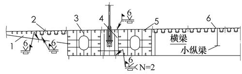
Figure 1 shows the standard section of the steel box girder
1. Cantilever 2. Block position line 3. Main longitudinal beam A 4. Anchor box unit 5. Main longitudinal beam B 6. Main longitudinal beam B 7. Main bridge center line
According to the structural characteristics of the steel box girder of the bridge, the full-bridge steel box girder is reasonably divided and segmented considering the transportation conditions and the construction erection scheme of the construction site. The manufacture of steel box girder adopts “plate→plate unit→block→factory coating→main longitudinal beam tailoring→main longitudinal beam pre-assembly→steel box girder tailoring→annular seam welding→the last coat coating on the steel box girder surface "The way to produce.
The bridge steel beam is a fully welded steel box girder, the structure connection relationship is complicated, the weld seam is large, the welding workload is large, the welding deformation and residual stress generated are large, and the welding deformation is difficult to control. Welding is the key to the manufacture of the entire steel beam. The rationality of the process is directly related to the quality and progress of the steel beam. In order to ensure the welding quality and production schedule of the bridge, we will give priority to the advanced welding production process under the premise of economy, efficiency, safety and reliability.
2. Welding materials
The main structure of the steel box girder adopts Q345qD steel, which meets the requirements of GB/T1591—1994 “Low-alloy high-strength structural steelâ€. It is a kind of steel widely used in bridge steel structure and has good welding performance. The selected welding materials after the welding process qualification test are:
Submerged arc welding: H10Mn2 (φ5.0mm) + SJ101q;
Flux cored wire CO2 gas shielded welding: E501T-1 (φ1.2mm) + CO2;
Solid wire CO2 gas shielded welding: ER50—6 (φ1.2mm)+CO2;
Solid wire welding argon-rich gas protection automatic welding:
ER50—6 (φ1.6mm)+(Ar80%+CO220%);
Welding rod arc welding: E5015 (φ4.0mm).
While meeting the relevant standards, the welding materials have set a higher than standard control index with the supplier to ensure the diffusion of hydrogen and the low temperature impact toughness of the weld metal.
3. Welding process
According to the welding characteristics of the steel used in this bridge, the form of weld joints, and the quality requirements, the groove form, groove size, welding material and welding process selected for various joints shall be in accordance with JTJ041-2000 "Technical Specifications for Highway Bridge Construction" and TB10212. -2009 "Code for the manufacture of railway steel bridges" to develop a process evaluation test program for a comprehensive welding process qualification test. After the process evaluation test is passed, it is used as the basis for the preparation of the welding process documentation of the bridge. According to the block, section and manufacturing characteristics of the bridge steel beam, the bridge welding process mainly consists of two parts: welding and welding on site.
4. Welding of typical welds in the factory
According to the characteristics of the steel beam segmentation, the welded parts of the beam section of the beam section mainly include: bridge deck unit, main longitudinal beam, anchor box unit, beam, small longitudinal beam and cantilever unit.
(1) The welded U-shaped rib of the U-shaped rib of the bridge deck is a groove fillet weld between the top plate and the top plate. The design requires that the weld penetration of the groove between the U-shaped rib and the top plate is ≥80%, and all U-rib groove welds are strictly prohibited. leak. After the welding process qualification test, it is determined that the groove shown in Fig. 2 is opened, and the U-rib weld of the automatic welding ship position in the same direction is protected by the molten gas mixed gas with a small heat input.
The penetration quality of the weld is the key to the quality of the orthotropic plate. To ensure the quality of the weld, the following welding process points are formulated:
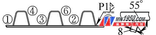
Figure 2 U rib welding groove
Note: 1 to 6 are welds
First, according to the heat input, stress distribution and deformation trend in the welding process of the plate unit, summarize the law of welding deformation, determine the amount of anti-deformation, design and manufacture the U-rib welded anti-deformation tire frame, and adopt the "anti-deformation" technology on the tire frame. Control the welding deformation of the U rib block unit. The anti-deformation tooling is shown in Figure 3, and all the welding is performed on this tire frame.
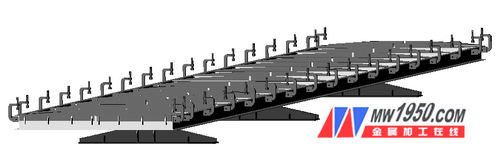
Figure 3 U-rib welding anti-deformation tooling
Second, the welding direction and the welding sequence are controlled. The general principle is to alternately weld in the same direction to avoid excessive deformation caused by concentrated heat of the rod.
Third, the dry elongation of the wire has a great influence on the penetration depth. At the same time, it is easy to weld when the arc is straight to the root of the groove. The dry elongation of the U-rib weld is preferably controlled to 20 to 25 mm.
Fourth, the penetration and forming of the U-rib groove fillet weld are very sensitive to the operation change. During the welding process, the arc state must be tracked at any time, and the position of the welding wire should be adjusted in time. The arc should not be directly aligned with the root of the groove, and should be offset from the groove. The roots are 2 to 3 mm toward the panel side.
Fifth, the semi-automatic welding of the flux-cored wire CO2 is allowed within 150 mm of the U-rib end, and the joint is ground to a 1:5 slope before welding. After the welding is completed, the joint is ground to a smooth transition, and the steel liner is ground to a steepness of 1:5.
(2) Four main welds of the main longitudinal beam The main longitudinal beam of the main longitudinal beam and the four main welds of the top and bottom are both penetration welds (see Figure 4). The thickness of the web is thin. After the welding process qualification test, select one side. V-shaped groove, the groove is opened on the inside of the box, and the flux-cored wire CO2 gas shielded welding is used. First, it is welded on the inside of the box, and the outer side is welded with carbon arc gouging to clear the root. The welding is carried out in the order of multi-person segmentation.
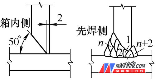
Fig. 4 shows the penetration weld of the web of the main longitudinal beam and the top and bottom plates
(3) The structure of the anchor box of the anchor box is complicated, and the weld seam is highly restrained. It is the most important part of the whole bridge. In order to improve the mechanical properties of the part, the welding process is evaluated. Core wire CO2 gas shielded welding, the structure is shown in Figure 5.
According to the structure of the anchor box, due to the limited space, a single-sided welding double-sided forming process is adopted, and the groove is as shown in FIG. 6. The back of the groove is welded with the corresponding pad, the back side of the grooved plate is welded with a steel pad, the back of the anchor plate and the connecting plate are welded with a ceramic pad, and the gap is 6mm during assembly. Arrange and clean between layers and adjust the welding sequence in time.
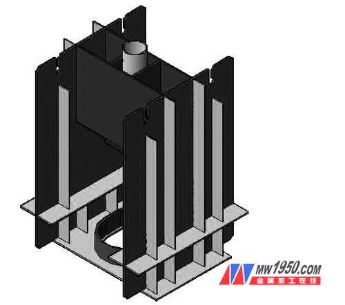
Figure 5 anchor box structure
Note: 1, 2 for welds
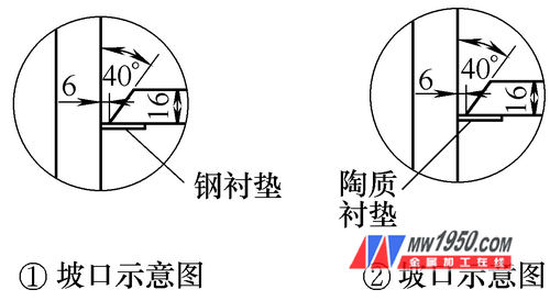
Figure 6 Anchor box structure groove
5. Site welding
According to the construction plan of the construction site, the main welds of each joint are mostly penetration welds, and the local operation space is limited. Therefore, the welding has great difficulty, not only to ensure the inherent quality of the weld, but also to ensure the minimum welding deformation. A large number of CO2 gas shielded welding is used to ensure the connection accuracy of the structure.
(1) Site welding sequence and precautions The overall welding sequence of the site is to weld the longitudinal joint welds between the units first, and then weld the transverse joints between the beam sections, following the principle of symmetrical, uniform and synchronous welding. Arrange multiple people to weld symmetrically at the same time, and observe the deformation at any time, pay attention to adjust the welding sequence.
Welding sequence of bridge deck hoisting unit: corner joint weld of secondary longitudinal beam and beam → longitudinal butt weld between bridge decks → beam, secondary longitudinal beam and bridge deck fillet weld.
Main longitudinal beam welding sequence: anchor box, connecting plate bottom plate and main longitudinal beam box bottom plate butt weld → anchor box and main longitudinal beam box joint welding joint → connecting plate and main longitudinal beam box joint welding seam → main longitudinal beam The butt weld of the top plate and the main longitudinal beam box → the anchor box, the connecting plate and the main longitudinal beam top plate weld.
The overall welding sequence of the steel box girder: the butt weld of the beam and the main longitudinal beam joint → the butt weld of the bridge deck and the main longitudinal beam top plate → the joint of the cantilever and the main longitudinal beam.
Welding sequence of transverse interface of steel box girder: transverse weld of main longitudinal beam floor → transverse weld of main longitudinal girder → transverse weld of main longitudinal girder roof → transverse weld of secondary longitudinal beam → transverse weld of bridge deck → transverse weld of cantilever → Inlay section welds.
The horizontal interface welding of the bridge should pay attention to the following matters: 1 The welding direction of each interface should be symmetrically welded on both sides. 2 In order to reduce the additional stress and welding residual stress caused by welding, the general principle of welding direction is: the transverse weld should be symmetrically welded from the central axis of the bridge to the two sides; the long weld at one end has a free end, which can be applied from the other end. The welding advances toward the free end; it is divided into medium and symmetric sections. 3 After the non-destructive testing of the butt welds of the bridge deck, bottom plate and web is qualified, the U-rib and slat ribs can be assembled.
Pay attention to the weld bead arrangement during welding. The weld bead arrangement should be staggered up and down so as to form crystals which are interwoven into a network, so that the weld impurities are segregated and dispersed, which is beneficial to improve the low temperature impact toughness of the weld.
(2) Welding joints between the welded anchor box unit and the main longitudinal beam of the typical weld of the construction site: the joint weld between the anchor box unit and the main longitudinal beam is mainly the butt weld of the bottom plate, the connecting plate and the bottom plate and the web of the main longitudinal beam. T-shaped penetration fillet welds, etc. Firstly weld the butt weld of the bottom plate, and weld the joint box of the anchor box and the web of the main longitudinal beam and the fillet weld of the bottom plate after the inspection.
According to the installation situation on site, combined with the manufacturing difficulty, after the welding process is evaluated, the joint of the joint is single-sided and single-sided V-shaped groove. The groove is opened in the anchor box unit, and the welding method is the flux-cored wire CO2 gas shielded welding. The single-sided welding double-sided forming process is adopted for the bottom plate of the anchor box and the bottom plate of the main longitudinal beam. As shown in Fig. 7, the ceramic liner is attached to the back of the groove before welding; the T-shaped melting of the anchor box connecting plate and the main longitudinal beam web and the bottom plate The through-hole weld is first welded on the groove side, and the carbon arc gouging is used to clear the root before the back welding, paying attention to the quality of the root.
The main longitudinal beam and the beam are connected to the weld: the joint weld between the main longitudinal beam and the beam includes the beam bottom plate and the main longitudinal beam floor weld, the beam web and the main longitudinal beam beam joint plate weld are all butt welds, respectively Single-sided V-shaped and double-sided V-shaped groove are selected, the root is left with 6mm gap, the back is affixed with ceramic liner, and the solid-core welding wire CO2 gas is used for welding welding. The welding is required to be symmetrically welded on both sides of the reference beam. In order to ensure the uniform shrinkage of the welds on both sides, and to monitor the deformation trend at any time, the welding direction and welding sequence are dynamically adjusted.
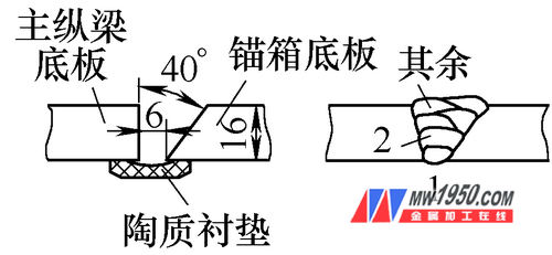
Figure 7 shows the weld seam between the anchor box bottom plate and the main longitudinal beam bottom plate
Note: 1, 2 is the welding pass
Lateral butt weld of main longitudinal beam: main longitudinal beam transverse connection main weld welding sequence: 1 web butt weld. 2 base plate butt weld. 3 top plate butt welds. 4 The web and the top plate are penetrated through the fillet weld, as shown in Fig. 8. The circled numbers in the figure indicate the welding sequence, and the arrows indicate the welding direction.
Both the web and the bottom plate are welded by a solid-core CO2 gas-shielded semi-automatic single-side welding process. The groove is shown in Fig. 9. When the unequal thickness is butt jointed, the thick plate is processed by 1:8 slope.
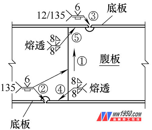
Figure 8 shows the horizontal connection of the main longitudinal beam
Note: 1 to 5 are welding sequences

(a) unequal thickness butt joint (b) equal thickness butt joint diagram 9
Before the welding of the web and the top and bottom plate penetration welds, the flank and the lap joints of the butt welds of the web are gouging and repaired, and the two ends of the butt welds of the web are ground to the penetration of the web and the top and bottom. In the form of groove, the lap joint is ground to a 1:5 slope, and the semi-automatic welding is protected by solid CO2 gas. After the welding is completed, the lap joint is smoothed and smoothed.
Top butt weld: the vertical and horizontal joints of the top plate are made of single-sided welding and double-sided forming process. The semi-automatic welding and bottoming welds are protected by solid-core welding wire CO2 gas, and the submerged arc welding fills the cover surface. 10 is shown.
Note when welding: 1 The bottom weld is welded by CO2 gas shielded welding with two layers, thickness ≥ 8mm. The first layer of bottom welding uses small heat input swing welding to ensure good fusion; the second layer of bottom welding heat input can be appropriately increased, using narrow bead welding. 2 Submerged arc welding The first layer of the filling welding shall take the lower limit of the current to prevent the welding leakage, and the voltage will be upper limit when the submerged arc is welded. 3 Control the heat input and the interlayer temperature during the submerged arc welding to ensure the mechanical properties of the weld, cover the surface with multiple covers, control the residual height and the appearance of the weld. 4 In order to control the total width of the beam section, a 3mm shrinkage is reserved for each longitudinal butt weld of the top plate before welding, and the total width of the transverse shrinkage after welding is controlled within the acceptance criteria.
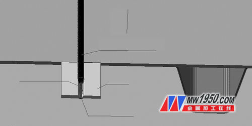
Figure 10 shows the butt weld
When it is not possible to cover the surface by submerged arc welding, the solid welding wire CO2 gas shielded welding surface can be used, the gas shielded welding bead is welded first, and then the submerged arc welding cover bead is welded (the gouging at the joint before welding) A 1:5 slope is applied, and 20 mm is lapped and welded again, and the lap joint is smoothed after welding, as shown in Fig. 11.
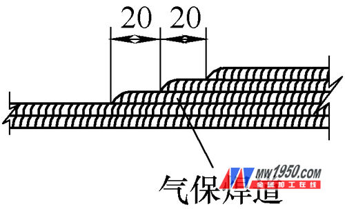
Figure 11 Gas shielded welding surface
Welding of U-shaped ribs and beam webs: the intersection of U-shaped ribs and beam webs, due to the load of reciprocating action, the stress is more complicated. In order to improve the fatigue resistance here, after the plates are in place, the Solid-core welding wire CO2 gas shielded welding, no arcing or arc-extinguishing at the over-welded hole, and the fillet weld between the U-rib and the web of the beam is carried out from the bottom up. The ends of the U-rib and beam web fillet are angled and the unevenly formed areas are ground (see Figure 12).
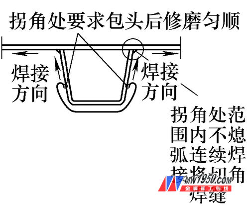
Figure 12 U-rib and beam web welds
Bridge slab U-shaped ribbed inlay welding: U ribs inlaid section welding sequence: 1 first weld U rib butt weld, as shown in Figure 13. 2 Grind the end of the butt weld to the same groove as the reserved section, and then weld the inlay section U and the groove fillet weld of the top plate.
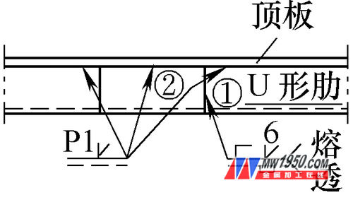
Figure 13 U rib embedded section welding
The welding method adopts solid-core welding wire CO2 gas shielded welding, U-rib jointing adopts single-side welding double-sided forming process, and the front side of welding is pasted with permanent steel liner, as shown in Fig. 14, the steel liner is continuously welded.
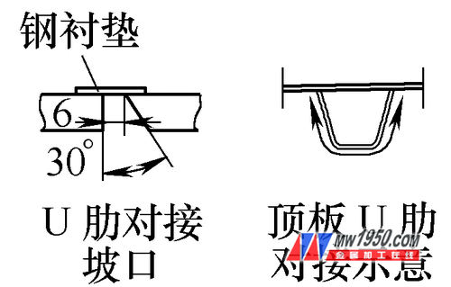
Figure 14 U rib butt weld
6. Welding inspection
(1) Appearance inspection of welds All welds are visually inspected after the weld metal is cooled. Welds shall not have defects such as cracks, unfused, welded tumors, slag inclusions, unfilled, arc pits and missing welds, and the quality shall comply with the acceptance criteria.
(2) Non-destructive testing of welds The welds are subjected to non-destructive testing after passing the visual inspection. The non-destructive testing is carried out 24 hours after the welding is completed. Among them: 100% ultrasonic + 10% X-ray inspection of the top and bottom butt welds and web transverse butt welds according to Class I weld; 100% penetration of fillet welds between the web and the top and bottom plates Ultrasonic flaw detection is tested according to Class II weld; the angle weld between the U-shaped rib and the top and bottom plates is welded. After welding, the magnetic powder is detected in the range of 1m at both ends of each weld, and the inspection level is Grade II.
Ultrasonic according to the test method according to GB11345-1989 "steel weld manual ultrasonic flaw detection method and flaw detection results classification", X-ray detection method according to GB3323-1987 "steel fusion welding butt joint radiography and quality classification" implementation, magnetic particle detection method according to JB /T6061—1992 “Identification of weld magnetic powder detection method and classification of defect magnetic marksâ€.
(3) Weld Destructive Test When welding main component products, add product welding test panels. After the product weld test plate weld has passed the appearance and flaw detection test, it is sampled for destructive test, joint tensile, side bend and weld metal low temperature impact test, and the mechanical properties of the weld are obtained to monitor the stability of the weld quality. Sex. For longitudinal butt welds, a set of welded test panels are made for every 30 strips; transverse butt welds are bridged laterally, and a set of welded test panels are made for every 10 welds.
7. Conclusion
The welding process selected for this scheme is reasonable, and the appearance and mechanical properties of the weld meet the acceptance criteria, ensuring the quality of the bridge.
Door Handle On Plate,Large Plate Door Handle,Bathroom Plate Door Handle,Aluminum Plate Door Handle
Wenzhou Shenghong Metal Products Co.,Ltd , https://www.shenghonglock.com