Interpretation of the new international standard for crankshafts and connecting rods in 2009
2022-11-01 14:06:48
The internal combustion engine crankshaft and connecting rod are the main moving parts on the internal combustion engine. In 2009, China's internal combustion engine crankshaft and connecting rod standards were upgraded from the mechanical industry standard to the national standard for the first time. The standard number and name are GB/T23339-2009 "Technical Conditions for Internal Combustion Engine Crankshaft" and GB/T23340-2009 "Technical Conditions for Connecting Rods of Internal Combustion Engines". . The two new national standards were simultaneously issued by the National Standardization Committee on March 19, 2009 and officially implemented on November 1, 2009.
GB/T23339-2009 "Technical conditions for internal combustion engine crankshaft"
The internal combustion engine crankshaft product standard was first issued in 1964 by the ministerial (agricultural machinery) standard, the standard number is NJ24, and was revised twice in 1974 and 1986. After the promulgation of China's "Standardization Law" in 1988, all standards in the machinery industry were collectively referred to as machinery industry standards in addition to national standards. Therefore, this standard was revised to the recommended machinery industry standard in 1993, and the standard number is JB/T6727. It has been used since its first revision in 2000.
The national standard number and name of the crankshaft are GB/T23339-2009 "Technical Conditions for Crankshaft of Internal Combustion Engines". This standard was proposed by the China Machinery Industry Federation. It is under the jurisdiction of the National Internal Combustion Engine Standardization Technical Committee and drafted by the Shanghai Internal Combustion Engine Research Institute. It specifies the technical requirements, inspection methods, inspection rules and marking, packaging, transportation and storage of internal combustion engine crankshafts. A reciprocating internal combustion engine crankshaft having a cylinder diameter of not more than 200 mm.
The comparison between the new standard and the original JB/T6727-2000 machinery industry standard is as follows.
1. Scope of application
The scope of application of the standard has not changed and is still applicable to reciprocating internal combustion engines with cylinder diameters less than or equal to 200 mm.
2. Technical requirements for steel crankshaft forgings
The national standard for crankshafts specifies the steel and crankshaft forgings for crankshafts. Compared with the 2000 version of the machinery industry standard, there are mainly the following changes:
(1) Added provisions allowing the use of non-tempered steel. The new standard clearly stipulates that it is recommended to use F40MnV non-tempered steel specified in GB/T15712 or other non-tempered steel grades for similar purposes. This will play a significant role in promoting the application of non-tempered steel, a green, energy-efficient, environmentally friendly green steel.
(2) In view of the national standard for testing non-metallic inclusions - GB/T10561 standard has been revised to the 2005 version, the new crankshaft standard will be used to assess the grade of various non-metallic inclusions using the JK rating chart, modified to use GB/ The T10561-2005 standard assesses the inclusion level. The grades of various types of inclusions have not changed, and the inclusions of Class A and Class B are not more than Grade 2.5, and the inclusions of Class C and D are not greater than Grade 1. However, the new standard for crankshafts eliminates the requirement that the sum of all types of inclusions be no greater than five.
(3) The regulations for the forging ratio have been adjusted. The crankshaft machinery industry standard stipulates the forging ratio of the crankshaft forgings to be not less than 7, and does not mention the forging ratio of the ingot. The new national standard of the crankshaft defines different forging ratios according to different parts of the crankshaft. According to the new national standard of the crankshaft, the forging ratio of the flange portion of the crankshaft should not be less than 1.5, and the rest should be no less than 2. And increased the forging ratio of steel ingots (not less than 7).
(4) The provisions for post-forging cooling and heat treatment of forgings have been added. The new national standard stipulates that the crankshaft forgings should be quenched or tempered or normalized, but only allowed to be repeated once, and the number of tempers is not limited. Crankshaft forgings using non-tempered steel can be normalized or controlled to cool.
(5) The upper limit of the hardness is increased. The hardness of the normalized crankshaft is modified from 163 to 241 HBW to 163 to 277 HBW. The hardness of the crankshaft for quenching and tempering is adjusted from 207 to 302 HBW to 207 to 320 HBW. In addition, the hardness regulations for non-quenched and tempered steel crankshafts have been increased. After the non-tempered steel crankshaft forgings are air-cooled, the hardness at the specified position of the pattern should be in the range of 207-277HBW.
In addition, it is worth noting that the sign of hardness is changed from the original "HBS" to "HBW". The symbol "HBS" indicates the Brinell hardness measured by using a hardened steel ball as an indenter, and the symbol "HBW" indicates the Brinell hardness measured by using a cemented carbide ball as an indenter. Since the current 2002 GB/T231 metal Brinell hardness test method national standard cancels the method of measuring the Brinell hardness using a quenched steel ball. Therefore, the crankshaft national standard (including the national standard for connecting rods) always uses the symbol "HBW" to indicate the Brinell hardness.
(6) There is no change in the straightness of the forgings. On the basis of the original, the provisions for the thermal alignment of the crankshaft forgings with a straightness of more than φ 5.0 mm per 1000 mm of the crankshaft are added.
(7) In terms of metallographic organization, the grain size level is changed from the original 4 to 10 levels to not less than 4, that is, the upper limit of the grain size level is eliminated. Another change is the addition of regulations for the metallurgical organization of non-quenched and tempered steel crankshafts. It is required that the grain size of the non-quenched and tempered steel crankshaft is not less than 4 grades, the metallographic structure should be pearlite + ferrite, and the Wei's structure is not allowed.
3. Technical requirements for ductile iron crankshaft castings
The new national standard of the crankshaft has no change in the regulations on the material, hardness and metallographic structure of the ductile iron crankshaft. Just two rules have been added. First, the regulations for normalizing and austempering of ductile iron crankshaft castings have been added; the second is to increase the straightness of ductile iron crankshaft castings. The new national standard of the crankshaft stipulates that the straightness of the common axis of each main journal of the crankshaft casting is not more than φ 4.0mm per 1000mm crankshaft; when every 1000mm crankshaft length is greater than φ 5.0mm, it should be thermally aligned.
4. Technical requirements for crankshaft surface treatment
(1) The recommended forging steel crankshaft is rounded and quenched, and the ductile iron crankshaft is nitrided or rounded and rolled to strengthen the fatigue strength of the crankshaft. This regulation is in line with the revised QC/T481 "Technical Conditions for Automotive Engine Crankshafts" issued in 2005.
The rules are consistent. At present, some forged steel crankshafts are still treated with nitriding, which is not worth promoting.
(2) The specification of the depth of the hardened layer of the crankshaft is reduced. After the surface of the forged steel crankshaft is quenched and tempered, the depth of the hardened layer is modified from 1.0 to 4.5 mm to 1.0 to 4.5 mm. After quenching and tempering on the surface of the ductile iron crankshaft, the depth of the hardened layer is changed from 1.5 to 4.5 mm to 1.0 to 4.5. Mm, the new national standard of the crankshaft, unifies the requirements of the forged steel crankshaft and the ductile iron crankshaft in the depth of the hardened layer.
(3) The new national standard will temper after induction hardening of the surface of the spheroidal graphite cast iron crankshaft. It must be tempered by the original requirements, and modified to allow the surface to be quenched and then tempered. That is to say, according to the new standard, the surface of the ductile iron crankshaft can be tempered after induction hardening, or it can be tempered.
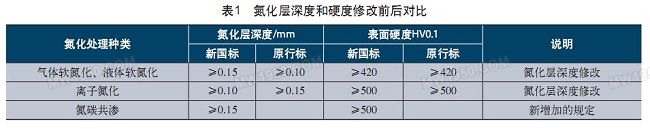
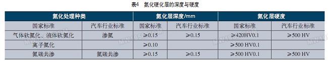
(4) The nitride layer depth specification was modified, and the depth and hardness requirements of the nitride layer treated by nitrocarburizing were increased. See Table 1 for comparison before and after modification.
(5) Increased requirements for surface oil holes. The distribution and size of the hardened layer and soft point (unhardened) at the oil hole on the journal surface are specified as specified. After quenching at the oil hole, there must be no cracks.
(6) Supplementary surface quality requirements. The supplementary contents include: the transitional rounded corners of the main journal and the connecting rod journal and the crank should be smoothly transitioned, and there should be no obvious joints at the joint; the finished grinding surface is not allowed to be burned; the hardened layer of the crankshaft No indentations are allowed on the surface.
5. Inspection method
(1) The sampling position of the hardness, depth and width of the hardened layer of the surface hardened crankshaft is modified. It has been previously specified that the hardness, depth and width of the hardened layer are radially cut from the main journal and the neck of the connecting rod at 4 mm from the crank arms at both ends. This specific rule has now been removed and only sampling on the crankshaft body is required.
(2) The inspection method for the depth of the hardened layer of the crankshaft is modified. It has been previously stipulated that the depth of the hardened layer of the crankshaft can be determined by three methods: corrosion method, metallographic method and hardness method. Only metallographic methods and hardness methods are now allowed. When the test results of the two methods are contradictory, the hardness method shall prevail. However, the new national standard has completely described the metallographic method and the hardness method, which is more specific than the original one. See Table 2 for a comparison of the two.
(3) The provisions of the test method for the hardness of the hardened layer are modified. The new national standard specifies the hardness method and the metallographic method. Previously, the hardness method and the corrosion method were specified. In other words, the new national standard adjusts the original corrosion method to the metallographic method. The range of measuring the width of the hardened layer is clearly defined in the metallographic method. This range should be from 100% martensite to 50% martensite + 50% troostite.
(4) The provisions of the method for testing the depth of the nitrided nitride layer are modified. In addition to the hardness method and metallographic method specified in GB/T11354 "Determination of Nitrided Layer of Steel Parts and Metallographic Tissue Inspection", the original machinery industry standard also stipulates an etching method. The new national standard for the crankshaft eliminated the corrosion method and clearly stated that the spheroidal graphite cast iron crankshaft can only be used to examine the depth of the nitrided layer by the metallographic method, which is not available in the old standard. In other words, according to the new national standard, the forged steel crankshaft can be used to measure the depth of the nitrided layer by the hardness method or the metallographic method, but the ductile iron crankshaft must use the metallographic method to detect the depth of the nitrided layer. This provision should be brought to the attention.
(5) In terms of the specification of the surface roughness measurement method, the provision of "measured by the surface roughness meter" has been added. Therefore, the surface roughness of the main journal and the connecting rod journal should be measured by the surface roughness meter whenever possible.
(6) The requirement for the manufacturer to periodically check the crankshaft is cancelled. Because the periodic sampling of the crankshaft is a quality control activity inside the crankshaft manufacturing plant. It is obviously not appropriate to make provisions in this standard.
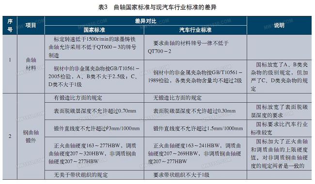
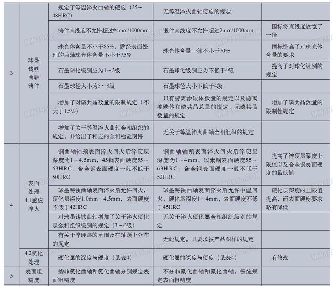
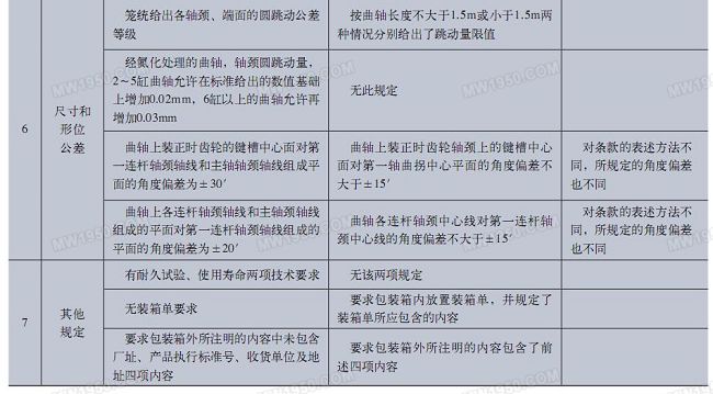
6.Compared with QC/T481-2005 "Technical Conditions of Automobile Engine Crankshaft"
Prior to the introduction of the national standard for internal combustion engine crankshafts, the crankshaft industry standard, in addition to the above-mentioned JB/T6727 machinery industry standard, also has an automotive industry standard specifically for the technical conditions of automotive engine crankshafts. The current version of the automotive industry standard is QC/T481-2005 "Technical Conditions for Automotive Engine Crankshafts". The main differences between the newly released crankshaft national standards and QC/T481-2005 are shown in Table 3.
GB/T23340-2009 "Technical conditions for connecting rods of internal combustion engines"
1. Overview of connecting rod standards
GB/T2 3 3 4 0-2 0 0 9 "Technical Conditions for Connecting Rods of Internal Combustion Engines" is based on the mechanical industry standard of JB/T6721-1993 "Technical Conditions for Connecting Rods of Internal Combustion Engines", by Shanghai Internal Combustion Engine Research Institute and two The relevant enterprises jointly drafted and were under the jurisdiction of the National Internal Combustion Engine Standardization Technical Committee. The national standard basically maintains the structure of the original machinery industry standard, the technical requirements, inspection methods, inspection rules and signs, packaging, transportation, and for the forged steel connecting rods of the internal combustion engine (including the connecting rod body, the connecting rod cover and the connecting rod bushing). Regulations have been made for storage, etc., which are applicable to forged piston internal combustion engine connecting rods with a cylinder diameter of not more than 200 mm.
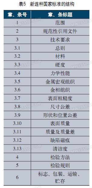
2. The structure of the new standard
As shown in Table 5.
3. The main difference from the original JB/T6721-1993
(1) Technical requirements First of all, the new national standard clearly includes 42CrMo grade alloy steel in the standard. The original machinery industry standard only mentioned the three steel grades of 45, 40Cr and 35CrMo. At present, more and more connecting rods are made of 42CrMo grade alloy steel. The national standard for connecting rods is adapted to this reality.
Second, the national standard of the connecting rod no longer specifies the hardness of the connecting rod after quenching and tempering, and the hardness value of the connecting rod is uniformly specified. The hardness of the link body and the connecting rod cover which are subjected to quenching and tempering is required to be 207 to 320 HBW. There is no change in the specification of the hardness difference, and it is still 35 HBW.
Third, the mechanical performance indicators are clearly given, which is not what the original machinery industry standards do. For the connecting rod, the mechanical performance index is an important technical requirement. At present, most of the internal combustion engine connecting rod product drawings have only hardness requirements, and there are no other mechanical performance requirements. The main reason is that China's original connecting rod machinery industry standards lack this provision. For the first time, the new national standard unifies the mechanical performance requirements of the connecting rod, which will have great significance for ensuring the intrinsic quality of the connecting rod. The mechanical performance indicators specified in the new national standard are shown in Table 6.
As can be seen from Table 6, the sign of the impact toughness is represented by K U2 . The symbol of previous impact toughness is "A KU" or "A KV". GB/T229-2007 "Metal material Charpy pendulum impact test method" has changed the symbol of impact toughness to "K U2" or "K V2". Among them, the letter K means "absorbed energy", the letter U (or V) means U-shaped notch (or V-shaped notch), and the lower foot number 2 or 8 means that the radius of the pendulum blade is 2mm or 8mm.
Fourth, the allowable height value of the flash of the connecting rod blank is tightened. The height of the parting surface flash is changed from no more than 0.8mm to no more than 0.5mm. Other surface quality requirements have not changed.
Fifth, the regulations on the life and warranty period of the connecting rod were cancelled.
(2) Inspection method There are two major differences in the regulations on the connection inspection method. First, the individual dimensions of the No. 3 mechanical property test specimen were modified. Change the width B of the chuck from the original "(22 ± 0.1) mm" to "(28 ± 0.1) mm", and change the original sample thickness dimension a 0 from the original "(3 ± 0.02) mm" to "(2 ± 0.02) mm". The second is to modify the type of corrosion solution used to detect the macroscopic microstructure of the longitudinal section of the connecting rod. The original was etched with a 3% to 5% nitric acid solution to be etched with a 50% hydrochloric acid solution.
(3) Differences in packaging and marking The national standard for connecting rods requires that the connecting rods be packaged in boxes. This is not the standard of the original machinery industry. The connecting rods packed in the box are transported in the box. The requirements for the total mass of the box did not change and remained no more than 50 kg per case. In addition, the new national standard also requires a corresponding label on the package. The contents of the logo include: manufacturer's name, trademark and address, product name, material and model number, quantity, product quality grade, packaging date and rust-proof validity period, and implementation standard number. The corresponding sign is still to be made outside the box. The logo on the outside of the box has more than “marker gross weightâ€, “receipt unit and addressâ€, “careful and light, moisture-proof words or symbolsâ€, and needs to identify “factory date†instead of "Packaging date".
Conclusion
With the development of the economy, the application of modern vehicles such as automobiles has become more and more, and other internal combustion engine machinery has been more and more widely developed and used. As the main components and security parts of the internal combustion engine, the crankshaft and connecting rod are necessary to unify the technical requirements nationwide. The release of the national standard for crankshafts and connecting rods of internal combustion engines is of great significance for ensuring the quality of crankshafts and connecting rods and ensuring the safe operation of internal combustion engine machinery. The newly released internal combustion engine crankshaft and connecting rod two national standards technical content is more complete, the organization is more clear, and pay attention to the coordination with the current relevant standards. Compared with the original machinery industry standards, the specifications of the technical indicators are wide and strict, and the standard terms are increased or decreased. In particular, the crankshaft standard has increased the content of non-tempered steel and the link standard has increased the mechanical performance index, which are historical changes.
In addition, the author believes that there are still several shortcomings in the new national standard for crankshafts.
(1) Terminology is not consistent with current national standards. If the "crank pin" is still referred to as "link journal", this is not in accordance with the current GB/T6809.3-2006 "Reciprocating internal combustion engine parts and systems terminology part 3: main moving parts". For example, the “geometric tolerance†is still referred to as “shape toleranceâ€, the “display†of magnetic particle inspection is still referred to as “magnetic markâ€, etc., which are in contradiction with the current terminology national standard. As a product standard, the terminology should be consistent with the corresponding terminology standard.
(2) It is unfortunate that the 42CrMo material is not mentioned in the national standard of the crankshaft. At present, this material has been widely used on crankshafts and has been included in one of the main recommended steels by the upcoming national standards for crankshaft materials. Therefore, the material should be explicitly included in the crankshaft product standard.
(3) The specification of the quenching hardness of the alloy steel crankshaft surface is somewhat high. In some industrialized countries, the standard is only specified to be 45 to 50 HRC, while China has been stipulated as 50 HRC or more, which is worthy of further discussion.
With the issuance and implementation of the national standard for internal combustion engine crankshafts, the original JB/T6727-2000 "Technical Conditions for Crankshaft of Internal Combustion Engines" and JB/T6721-1993 "Technical Conditions for Connecting Rods for Internal Combustion Engines" will be automatically abolished. The QC/T481-2005 "Technical Conditions for Automotive Engine Crankshafts" can be retained but needs further revision. Because the automotive industry standard is a special standard for automotive engine crankshafts, and the newly released national standard is a common standard. However, the technical indicators in the industry standards cannot be lower than the requirements of national standards. Some technical requirements in QC/T481 are lower than the new national standards. Therefore, if you retain the standard you will need to revise it.
GB/T23339-2009 "Technical conditions for internal combustion engine crankshaft"
The internal combustion engine crankshaft product standard was first issued in 1964 by the ministerial (agricultural machinery) standard, the standard number is NJ24, and was revised twice in 1974 and 1986. After the promulgation of China's "Standardization Law" in 1988, all standards in the machinery industry were collectively referred to as machinery industry standards in addition to national standards. Therefore, this standard was revised to the recommended machinery industry standard in 1993, and the standard number is JB/T6727. It has been used since its first revision in 2000.
The national standard number and name of the crankshaft are GB/T23339-2009 "Technical Conditions for Crankshaft of Internal Combustion Engines". This standard was proposed by the China Machinery Industry Federation. It is under the jurisdiction of the National Internal Combustion Engine Standardization Technical Committee and drafted by the Shanghai Internal Combustion Engine Research Institute. It specifies the technical requirements, inspection methods, inspection rules and marking, packaging, transportation and storage of internal combustion engine crankshafts. A reciprocating internal combustion engine crankshaft having a cylinder diameter of not more than 200 mm.
The comparison between the new standard and the original JB/T6727-2000 machinery industry standard is as follows.
1. Scope of application
The scope of application of the standard has not changed and is still applicable to reciprocating internal combustion engines with cylinder diameters less than or equal to 200 mm.
2. Technical requirements for steel crankshaft forgings
The national standard for crankshafts specifies the steel and crankshaft forgings for crankshafts. Compared with the 2000 version of the machinery industry standard, there are mainly the following changes:
(1) Added provisions allowing the use of non-tempered steel. The new standard clearly stipulates that it is recommended to use F40MnV non-tempered steel specified in GB/T15712 or other non-tempered steel grades for similar purposes. This will play a significant role in promoting the application of non-tempered steel, a green, energy-efficient, environmentally friendly green steel.
(2) In view of the national standard for testing non-metallic inclusions - GB/T10561 standard has been revised to the 2005 version, the new crankshaft standard will be used to assess the grade of various non-metallic inclusions using the JK rating chart, modified to use GB/ The T10561-2005 standard assesses the inclusion level. The grades of various types of inclusions have not changed, and the inclusions of Class A and Class B are not more than Grade 2.5, and the inclusions of Class C and D are not greater than Grade 1. However, the new standard for crankshafts eliminates the requirement that the sum of all types of inclusions be no greater than five.
(3) The regulations for the forging ratio have been adjusted. The crankshaft machinery industry standard stipulates the forging ratio of the crankshaft forgings to be not less than 7, and does not mention the forging ratio of the ingot. The new national standard of the crankshaft defines different forging ratios according to different parts of the crankshaft. According to the new national standard of the crankshaft, the forging ratio of the flange portion of the crankshaft should not be less than 1.5, and the rest should be no less than 2. And increased the forging ratio of steel ingots (not less than 7).
(4) The provisions for post-forging cooling and heat treatment of forgings have been added. The new national standard stipulates that the crankshaft forgings should be quenched or tempered or normalized, but only allowed to be repeated once, and the number of tempers is not limited. Crankshaft forgings using non-tempered steel can be normalized or controlled to cool.
(5) The upper limit of the hardness is increased. The hardness of the normalized crankshaft is modified from 163 to 241 HBW to 163 to 277 HBW. The hardness of the crankshaft for quenching and tempering is adjusted from 207 to 302 HBW to 207 to 320 HBW. In addition, the hardness regulations for non-quenched and tempered steel crankshafts have been increased. After the non-tempered steel crankshaft forgings are air-cooled, the hardness at the specified position of the pattern should be in the range of 207-277HBW.
In addition, it is worth noting that the sign of hardness is changed from the original "HBS" to "HBW". The symbol "HBS" indicates the Brinell hardness measured by using a hardened steel ball as an indenter, and the symbol "HBW" indicates the Brinell hardness measured by using a cemented carbide ball as an indenter. Since the current 2002 GB/T231 metal Brinell hardness test method national standard cancels the method of measuring the Brinell hardness using a quenched steel ball. Therefore, the crankshaft national standard (including the national standard for connecting rods) always uses the symbol "HBW" to indicate the Brinell hardness.
(6) There is no change in the straightness of the forgings. On the basis of the original, the provisions for the thermal alignment of the crankshaft forgings with a straightness of more than φ 5.0 mm per 1000 mm of the crankshaft are added.
(7) In terms of metallographic organization, the grain size level is changed from the original 4 to 10 levels to not less than 4, that is, the upper limit of the grain size level is eliminated. Another change is the addition of regulations for the metallurgical organization of non-quenched and tempered steel crankshafts. It is required that the grain size of the non-quenched and tempered steel crankshaft is not less than 4 grades, the metallographic structure should be pearlite + ferrite, and the Wei's structure is not allowed.
3. Technical requirements for ductile iron crankshaft castings
The new national standard of the crankshaft has no change in the regulations on the material, hardness and metallographic structure of the ductile iron crankshaft. Just two rules have been added. First, the regulations for normalizing and austempering of ductile iron crankshaft castings have been added; the second is to increase the straightness of ductile iron crankshaft castings. The new national standard of the crankshaft stipulates that the straightness of the common axis of each main journal of the crankshaft casting is not more than φ 4.0mm per 1000mm crankshaft; when every 1000mm crankshaft length is greater than φ 5.0mm, it should be thermally aligned.
4. Technical requirements for crankshaft surface treatment
(1) The recommended forging steel crankshaft is rounded and quenched, and the ductile iron crankshaft is nitrided or rounded and rolled to strengthen the fatigue strength of the crankshaft. This regulation is in line with the revised QC/T481 "Technical Conditions for Automotive Engine Crankshafts" issued in 2005.
The rules are consistent. At present, some forged steel crankshafts are still treated with nitriding, which is not worth promoting.
(2) The specification of the depth of the hardened layer of the crankshaft is reduced. After the surface of the forged steel crankshaft is quenched and tempered, the depth of the hardened layer is modified from 1.0 to 4.5 mm to 1.0 to 4.5 mm. After quenching and tempering on the surface of the ductile iron crankshaft, the depth of the hardened layer is changed from 1.5 to 4.5 mm to 1.0 to 4.5. Mm, the new national standard of the crankshaft, unifies the requirements of the forged steel crankshaft and the ductile iron crankshaft in the depth of the hardened layer.
(3) The new national standard will temper after induction hardening of the surface of the spheroidal graphite cast iron crankshaft. It must be tempered by the original requirements, and modified to allow the surface to be quenched and then tempered. That is to say, according to the new standard, the surface of the ductile iron crankshaft can be tempered after induction hardening, or it can be tempered.
(4) The nitride layer depth specification was modified, and the depth and hardness requirements of the nitride layer treated by nitrocarburizing were increased. See Table 1 for comparison before and after modification.
(5) Increased requirements for surface oil holes. The distribution and size of the hardened layer and soft point (unhardened) at the oil hole on the journal surface are specified as specified. After quenching at the oil hole, there must be no cracks.
(6) Supplementary surface quality requirements. The supplementary contents include: the transitional rounded corners of the main journal and the connecting rod journal and the crank should be smoothly transitioned, and there should be no obvious joints at the joint; the finished grinding surface is not allowed to be burned; the hardened layer of the crankshaft No indentations are allowed on the surface.
5. Inspection method
(1) The sampling position of the hardness, depth and width of the hardened layer of the surface hardened crankshaft is modified. It has been previously specified that the hardness, depth and width of the hardened layer are radially cut from the main journal and the neck of the connecting rod at 4 mm from the crank arms at both ends. This specific rule has now been removed and only sampling on the crankshaft body is required.
(2) The inspection method for the depth of the hardened layer of the crankshaft is modified. It has been previously stipulated that the depth of the hardened layer of the crankshaft can be determined by three methods: corrosion method, metallographic method and hardness method. Only metallographic methods and hardness methods are now allowed. When the test results of the two methods are contradictory, the hardness method shall prevail. However, the new national standard has completely described the metallographic method and the hardness method, which is more specific than the original one. See Table 2 for a comparison of the two.

(3) The provisions of the test method for the hardness of the hardened layer are modified. The new national standard specifies the hardness method and the metallographic method. Previously, the hardness method and the corrosion method were specified. In other words, the new national standard adjusts the original corrosion method to the metallographic method. The range of measuring the width of the hardened layer is clearly defined in the metallographic method. This range should be from 100% martensite to 50% martensite + 50% troostite.
(4) The provisions of the method for testing the depth of the nitrided nitride layer are modified. In addition to the hardness method and metallographic method specified in GB/T11354 "Determination of Nitrided Layer of Steel Parts and Metallographic Tissue Inspection", the original machinery industry standard also stipulates an etching method. The new national standard for the crankshaft eliminated the corrosion method and clearly stated that the spheroidal graphite cast iron crankshaft can only be used to examine the depth of the nitrided layer by the metallographic method, which is not available in the old standard. In other words, according to the new national standard, the forged steel crankshaft can be used to measure the depth of the nitrided layer by the hardness method or the metallographic method, but the ductile iron crankshaft must use the metallographic method to detect the depth of the nitrided layer. This provision should be brought to the attention.
(5) In terms of the specification of the surface roughness measurement method, the provision of "measured by the surface roughness meter" has been added. Therefore, the surface roughness of the main journal and the connecting rod journal should be measured by the surface roughness meter whenever possible.
(6) The requirement for the manufacturer to periodically check the crankshaft is cancelled. Because the periodic sampling of the crankshaft is a quality control activity inside the crankshaft manufacturing plant. It is obviously not appropriate to make provisions in this standard.
6.Compared with QC/T481-2005 "Technical Conditions of Automobile Engine Crankshaft"
Prior to the introduction of the national standard for internal combustion engine crankshafts, the crankshaft industry standard, in addition to the above-mentioned JB/T6727 machinery industry standard, also has an automotive industry standard specifically for the technical conditions of automotive engine crankshafts. The current version of the automotive industry standard is QC/T481-2005 "Technical Conditions for Automotive Engine Crankshafts". The main differences between the newly released crankshaft national standards and QC/T481-2005 are shown in Table 3.
GB/T23340-2009 "Technical conditions for connecting rods of internal combustion engines"
1. Overview of connecting rod standards
GB/T2 3 3 4 0-2 0 0 9 "Technical Conditions for Connecting Rods of Internal Combustion Engines" is based on the mechanical industry standard of JB/T6721-1993 "Technical Conditions for Connecting Rods of Internal Combustion Engines", by Shanghai Internal Combustion Engine Research Institute and two The relevant enterprises jointly drafted and were under the jurisdiction of the National Internal Combustion Engine Standardization Technical Committee. The national standard basically maintains the structure of the original machinery industry standard, the technical requirements, inspection methods, inspection rules and signs, packaging, transportation, and for the forged steel connecting rods of the internal combustion engine (including the connecting rod body, the connecting rod cover and the connecting rod bushing). Regulations have been made for storage, etc., which are applicable to forged piston internal combustion engine connecting rods with a cylinder diameter of not more than 200 mm.
2. The structure of the new standard
As shown in Table 5.
3. The main difference from the original JB/T6721-1993
(1) Technical requirements First of all, the new national standard clearly includes 42CrMo grade alloy steel in the standard. The original machinery industry standard only mentioned the three steel grades of 45, 40Cr and 35CrMo. At present, more and more connecting rods are made of 42CrMo grade alloy steel. The national standard for connecting rods is adapted to this reality.
Second, the national standard of the connecting rod no longer specifies the hardness of the connecting rod after quenching and tempering, and the hardness value of the connecting rod is uniformly specified. The hardness of the link body and the connecting rod cover which are subjected to quenching and tempering is required to be 207 to 320 HBW. There is no change in the specification of the hardness difference, and it is still 35 HBW.
Third, the mechanical performance indicators are clearly given, which is not what the original machinery industry standards do. For the connecting rod, the mechanical performance index is an important technical requirement. At present, most of the internal combustion engine connecting rod product drawings have only hardness requirements, and there are no other mechanical performance requirements. The main reason is that China's original connecting rod machinery industry standards lack this provision. For the first time, the new national standard unifies the mechanical performance requirements of the connecting rod, which will have great significance for ensuring the intrinsic quality of the connecting rod. The mechanical performance indicators specified in the new national standard are shown in Table 6.
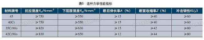
As can be seen from Table 6, the sign of the impact toughness is represented by K U2 . The symbol of previous impact toughness is "A KU" or "A KV". GB/T229-2007 "Metal material Charpy pendulum impact test method" has changed the symbol of impact toughness to "K U2" or "K V2". Among them, the letter K means "absorbed energy", the letter U (or V) means U-shaped notch (or V-shaped notch), and the lower foot number 2 or 8 means that the radius of the pendulum blade is 2mm or 8mm.
Fourth, the allowable height value of the flash of the connecting rod blank is tightened. The height of the parting surface flash is changed from no more than 0.8mm to no more than 0.5mm. Other surface quality requirements have not changed.
Fifth, the regulations on the life and warranty period of the connecting rod were cancelled.
(2) Inspection method There are two major differences in the regulations on the connection inspection method. First, the individual dimensions of the No. 3 mechanical property test specimen were modified. Change the width B of the chuck from the original "(22 ± 0.1) mm" to "(28 ± 0.1) mm", and change the original sample thickness dimension a 0 from the original "(3 ± 0.02) mm" to "(2 ± 0.02) mm". The second is to modify the type of corrosion solution used to detect the macroscopic microstructure of the longitudinal section of the connecting rod. The original was etched with a 3% to 5% nitric acid solution to be etched with a 50% hydrochloric acid solution.
(3) Differences in packaging and marking The national standard for connecting rods requires that the connecting rods be packaged in boxes. This is not the standard of the original machinery industry. The connecting rods packed in the box are transported in the box. The requirements for the total mass of the box did not change and remained no more than 50 kg per case. In addition, the new national standard also requires a corresponding label on the package. The contents of the logo include: manufacturer's name, trademark and address, product name, material and model number, quantity, product quality grade, packaging date and rust-proof validity period, and implementation standard number. The corresponding sign is still to be made outside the box. The logo on the outside of the box has more than “marker gross weightâ€, “receipt unit and addressâ€, “careful and light, moisture-proof words or symbolsâ€, and needs to identify “factory date†instead of "Packaging date".
Conclusion
With the development of the economy, the application of modern vehicles such as automobiles has become more and more, and other internal combustion engine machinery has been more and more widely developed and used. As the main components and security parts of the internal combustion engine, the crankshaft and connecting rod are necessary to unify the technical requirements nationwide. The release of the national standard for crankshafts and connecting rods of internal combustion engines is of great significance for ensuring the quality of crankshafts and connecting rods and ensuring the safe operation of internal combustion engine machinery. The newly released internal combustion engine crankshaft and connecting rod two national standards technical content is more complete, the organization is more clear, and pay attention to the coordination with the current relevant standards. Compared with the original machinery industry standards, the specifications of the technical indicators are wide and strict, and the standard terms are increased or decreased. In particular, the crankshaft standard has increased the content of non-tempered steel and the link standard has increased the mechanical performance index, which are historical changes.
In addition, the author believes that there are still several shortcomings in the new national standard for crankshafts.
(1) Terminology is not consistent with current national standards. If the "crank pin" is still referred to as "link journal", this is not in accordance with the current GB/T6809.3-2006 "Reciprocating internal combustion engine parts and systems terminology part 3: main moving parts". For example, the “geometric tolerance†is still referred to as “shape toleranceâ€, the “display†of magnetic particle inspection is still referred to as “magnetic markâ€, etc., which are in contradiction with the current terminology national standard. As a product standard, the terminology should be consistent with the corresponding terminology standard.
(2) It is unfortunate that the 42CrMo material is not mentioned in the national standard of the crankshaft. At present, this material has been widely used on crankshafts and has been included in one of the main recommended steels by the upcoming national standards for crankshaft materials. Therefore, the material should be explicitly included in the crankshaft product standard.
(3) The specification of the quenching hardness of the alloy steel crankshaft surface is somewhat high. In some industrialized countries, the standard is only specified to be 45 to 50 HRC, while China has been stipulated as 50 HRC or more, which is worthy of further discussion.
With the issuance and implementation of the national standard for internal combustion engine crankshafts, the original JB/T6727-2000 "Technical Conditions for Crankshaft of Internal Combustion Engines" and JB/T6721-1993 "Technical Conditions for Connecting Rods for Internal Combustion Engines" will be automatically abolished. The QC/T481-2005 "Technical Conditions for Automotive Engine Crankshafts" can be retained but needs further revision. Because the automotive industry standard is a special standard for automotive engine crankshafts, and the newly released national standard is a common standard. However, the technical indicators in the industry standards cannot be lower than the requirements of national standards. Some technical requirements in QC/T481 are lower than the new national standards. Therefore, if you retain the standard you will need to revise it.
Jiangsu Zhongyi Work Rigging Co., Ltd. , https://www.zy-rigging.com