Damage analysis of cemented carbide inserts during interrupted cutting (Fig.)
1 Introduction
Carbide tools appear cracks during cutting (especially during intermittent cutting) and cause damage. It has always been a problem that people are plagued. Correct understanding of the causes of cracks and taking appropriate precautions are the key to improving tool life and cutting performance. Related research literature indicates that when cutting at higher cutting speeds, the tool is prone to hot cracking and the edge chipping phenomenon increases. In this paper, the mechanism of cracking of cemented carbide tools during interrupted cutting is analyzed by cutting test. It is found that during the heating phase of the cutting cycle, the compressive thermal stress can cause local plasticity of the blade along the narrow zone of the rake face of the cutting edge. Deformation, then when the narrow zone is forced to cool again under the influence of the external elastic material, a tensile stress sufficient to cause visible cracks is generated, thereby verifying that thermal stress is the main cause of cracking of the cemented carbide tool.
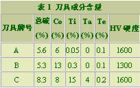
Table 1 Tool component content
2 Cutting test method and temperature measurement result
The cutting test was carried out at the Zhuzhou Cemented Carbide Factory Central Laboratory. The test method is to turn a rectangular cross-section test piece on a lathe to simulate intermittent cutting conditions. The test piece material was a carbon steel (hardness of about HV170) containing 0.6 to 0.8% Mn, 0.5% Ni, 0.5% Cr, and 0.5% Mo. The cutting tools are made of three grades of A, B and C respectively. The contents of the tool components are shown in Table 1. Tool cutting edge geometry: the lateral rake angle and the blade inclination angle are 0°, the lateral relief angle and the secondary relief angle are 6°, the residual angle is 0°, and the secondary declination is 6°.
Typical cutting conditions: cutting speed v = 95 m / min, feed rate f = 0.25 mm / r, depth of cut ap = 6 mm. Since the cutting test of the test piece having a cutting section of 50 mm × 250 mm was carried out, all the cemented carbide tools showed cracks after cutting for two minutes under the above cutting conditions, and thus it was determined as a typical cutting condition.
Tool-to-piece thermocouple method is used to measure tool-chip cross-section temperature. The typical recording curve of the measurement results is shown in Fig. 1. To find the minimum cycle temperature based on the change in the slope of the curve, take a record with the oscilloscope and find the minimum cycle temperature based on the magnified photo.
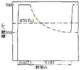
Figure 1 Tool-workpiece thermocouple typical record curve 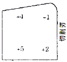

(a) bottom of the blade (b) top of the blade Figure 2 Location of the thermocouple
When analyzing the tool breakage mechanism, you need to know the temperature distribution inside the tool. To this end, the interface temperature of the blade is measured using a thermocouple and a thermistor during the cutting process, and the internal temperature of the tool can be calculated based on the blade interface temperature. The installation position of the thermocouple is shown in Figure 2. Typical temperatures measured during blade cutting are shown in Table 2 and Table 3, respectively.
During each cutting test, the cutting force of the tool was continuously recorded by a UV recorder, and the tangential force and the infeed force were measured using a calibration strain gauge mounted on the arbor.
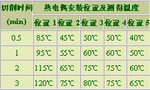
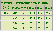
Table 2 Typical measurement results of thermocouples Table 3 Typical measurement results of thermocouples
(C grade cemented carbide with alumina gasket) (C grade cemented carbide with steel gasket)
Next page
BK7 Meniscus Lenses,meniscus lenses ,positive meniscus lenses, negative meniscus lenses ,meniscus concave lens
Our company can produce many kinds of flat convex Spherical Mirrors with different sizes, radii and base materials, flat convex spherical Mirrors, flat concave spherical mirrors, double convex spherical mirrors, double concave spherical mirrors, meniscus spherical mirrors and other ordinary spherical mirrors. Special spherical mirror can also be processed, such as: achromatic spherical mirror, aspheric surface and spherical mirror group.
Materials: optical glasses such as flint glass, ultraviolet fused quartz and infrared fused quartz, as well as optical crystal materials such as calcium fluoride (CaF2), germanium (Ge), Zinc selenide (ZnSe) and silicon (Si)
Focal length: ±5mm -- ±1000mm±1%
(Germany TIROPTICS OPTOMATIC2000 test)
Outer circle: 4mm -- 200mm±0.1mm
Center thickness tolerance: ±0.1mm
Center deviation: 3-5 points
Surface accuracy: /2@
Surface quality: 40/20
Effective diameter: 90%
Plating film: according to customer requirements can be coated
In addition, we have more than a thousand kinds of standard products, and some of the standard products in stock to meet your needs

Bk7 Meniscus Lenses,Meniscus Concave Lens,Meniscus Correction Lens,Meniscus Cylindrical Lens
Gold Dragon Optics Electronic Technology CO.,Ltd , https://www.golddragon-optics.com