Application and Classification of Video Matrix
2023-10-21 14:38:34
Video Matrix - Basic Functions and Requirements A matrix system should normally also include the following basic functions: character signal superimposition; decoder interface to control pan/tilt and camera; alarm interface; control host, and audio control box, alarm interface box, control keyboard And other accessories. For domestic users, character superposition should be all Chinese, to facilitate the use of operators who do not understand English, the matrix system also needs to support cascading to achieve higher capacity, in order to adapt to different users of the matrix system capacity requirements, matrix The system should support modular and plug and play (PnP), which can be achieved by adding or subtracting video input and output cards.
The development direction of the matrix system is multi-functional, large-capacity, networked, and remote switching. In general, the capacity of the matrix system reaches 64×16 which is a large capacity matrix. If a larger capacity matrix system is needed, it can also be achieved by cascading multiple matrix systems. The greater the capacity of the matrix, the higher the required technical level and the greater the difficulty of the design.
Category <br> <br> matrix of image signal with the development of technology, and improve the human visual audio and video; image signal transmission through the several stages of development, from AV Video to composite, component (YPbPr), then VGA signal, now to DVI and HDMI, DISPLAYPORT, etc.; In this process, due to the need to form a signal matrix switch, so that there is a corresponding matrix switcher in each signal phase; Now with IP technology and images The development of compression technology forms a virtual matrix switcher for multimedia streaming (based on MPEG-4, H2.64) exchange;
Divided into the form of transmission signal: analog matrix switcher and digital matrix switcher;
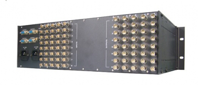
The analog matrix switcher is as follows:
The function of the matrix switcher is to transmit one or more video and audio signals to one or more display devices respectively, so we can classify the matrix switchers according to different signal sources. That is, the type of the matrix switcher is determined depending on the signal to be divided. The matrix switcher can be divided according to the type of signal source: VGA, AV, V, YPbPr matrix switcher and so on. For example: VGA matrix switcher is a matrix switcher with input and output signals of [] VGA signal. Other types can be analogized and will not be described here. The following will focus on the type of signal source.
VGA matrix:
VGA (Video Graphics Array), which is a display graphics array, is a computer display standard using analog signals proposed by IBM in 1987. VGA supports simultaneous display of 16 colors or 256 shades of gray at a higher resolution of 640X480 while simultaneously displaying 256 colors at a resolution of 320X240. VGA has quickly become popular because of its good performance. Vendors are expanding on the basis of VGA, such as increasing memory to 1M and enabling it to support higher resolutions such as 800X600 or 1024X768. These expansion modes are called VESA (Video Electronics). The Standards Association, the Video Electronics Standards Association's Super VGA mode, or SVGA for short, now supports SVGA mode for both video cards and monitors.
The composition of the VGA signal is divided into five types: RGBHV, which are the red, green, and blue primary colors and the line field sync signals. VGA transmission distance is very short. In order to transmit farther distances in the actual project, people disconnect the VGA cable, separate the RGBHV five kinds of signals and transfer them with five coaxial cables respectively. This transmission method is called RGB transmission. This signal is also called RGB signal. In fact, there is no difference between RGB and VGA.
VGA interface, also called D-Sub interface. The VGA interface is a D-type interface with a total of 15 pins empty, divided into three rows, five in each row. The VGA interface is the most widely used type of interface on the graphics card. Most graphics cards have such an interface. At present, most computers and external display devices are connected through an analog VGA interface. The computer internally generates digital display image information and is converted into R, G, and B primary color signals and lines by the digital/analog converters in the graphics card. Field synchronization signal, the signal is transmitted to the display device through the cable.
RGB matrix:
The composition of the VGA signal is divided into five types: RGBHV, which are the red, green, and blue primary colors and the line field sync signals. VGA transmission distance is very short. In order to transmit farther distances in the actual project, people disconnect the VGA cable, separate the RGBHV five kinds of signals and transfer them with five coaxial cables respectively. This transmission method is called RGB transmission. This signal is also called RGB signal, in fact, the signal is essentially no difference between RGB and VGA.
RGB transmission uses BNC plus coaxial cable transmission. The RGB cable has 5 connectors for receiving red, green, blue, horizontal sync and vertical sync signals. The BNC connector can insulate the video input signal, so that the interference between the signals is reduced and the signal bandwidth is larger than the normal D-SUB. The best signal response effect can be achieved.
AV matrix:
AV port (also called composite port) is a composite video connector, which is a common port used by home audio and video appliances to transmit analog video signals such as NTSC, PAL, and SECAM. The AV port is usually a yellow RCA port, with two red and white RCA ports transmitting the audio. European televisions usually use SCART ports instead of RCA ports. However, SCART is designed to carry better RGB signals than YUV, and it is also used to connect monitors, video games or DVD players. In professional applications, BNC ports are also used for better signal quality.
Transmitting in the AV port are the three source elements of the analog TV signal: Y, U, V, and the pulse signal as the synchronization reference. Y represents the brightness of the image (also known as brightness), and it contains sync pulses. As long as there is a Y signal, black and white TV images can be seen. Between the U signal and the V signal carries the color data, U and V are first mixed into two sets of orthogonal phases in a signal (the mixed signal is called chrominance), and then added to the Y signal. total. Since Y is the fundamental signal and UV is mixed with the carrier, this summation action is equivalent to division multiplexing.
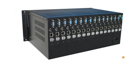
The digital matrix switcher follows the DVI matrix:
DVI (Digital Visual Interface) interface, namely digital video interface. It is an interface launched by DDWG (Digital Display Working Group) formed by companies such as Silicon Image, Intel, Compaq, IBM, HP, NEC, and Fujitsu in 1999. standard.
The DVI interface is based on the technology of the PanalLink interface of Silicon Image, and is based on the TMDS (Transition Minimized Differential Signaling) electronic protocol as the basic electrical connection. TMDS is a differential signal mechanism that can encode pixel data and pass it through a serial connection. The digital signal generated by the video card is encoded by the transmitter in accordance with the TMDS protocol and sent to the receiver through the TMDS channel, which is then decoded and sent to the digital display device.
A DVI display system includes a transmitter and a receiver. The transmitter is the source of the signal, which can be built into the graphics chip, or it can appear on the graphics card PCB in the form of an additional chip; and the receiver is a circuit on the display, it can accept digital signals, decode it and pass it Through the digital display circuit, the signal from the video card becomes the image on the display.
The current DVI interface is divided into two types:
One is the DVI-D interface, which can only receive digital signals. There are only 3 rows and 8 columns with 24 pins on the interface. One of the pins in the upper right corner is empty. Not compatible with analog signals. The other is a DVI-I interface that is compatible with both analog and digital signals. Compatible with analog signals does not mean that the analog signal interface D-Sub interface can be connected to the DVI-I interface, but must use an adapter to use, usually the graphics card with this interface will have the relevant adapter.
DVI signal, HDCP signal and HDMI signal For VGA signals, the signal channels are essentially the same if they exclude various protocols, and they are all DVI signals. So first introduce the characteristics of DVI signal.
In the analog display mode, the digital RG.B signal (8-bit parallel signal) to be displayed is D/A-converted into an analog signal in the video card, transmitted to the display after being transmitted, and then processed to drive the RG.B electron gun and displayed on the fluorescent screen. The whole process is simulated. The digital display mode is different, the analog RGB signal reaches the display device (LCD or DLP, PDP, etc.) after A / D processing, converted to digital signals, and then by the digital signal in the TFT LCD sourcedriver through the DAC conversion into analog signal control The liquid crystal panel transmits or reflects light or the DMD chip reflects light or emits light from the plasma to achieve the display effect. In this process, there is obviously a conversion process from digital → analog → digital → analog. The signal loss is large (one A/D, D/A process will lose 6dB in frequency spectrum, and the maximum bandwidth is reserved as 1/1 of the pixel clock. 2), and there will be problems such as smearing, blurring, ghosting and other transmission problems. Currently, computer graphics cards with digital interfaces are quite common. Even notebook computers are equipped with DVI interfaces, and more and more devices in display devices have digital signal interfaces. Therefore, the digital-to-digital application environment has matured.
In DVI principle, the RGB digital signal to be displayed is combined with the HV signal, and each pixel is digitally encoded according to the minimum non-return-to-zero encoding method and the digital signal is converted into a series of RGB digital signals. Four signals, such as the code stream and the pixel clock, are transmitted in a balanced manner. The rate of each channel is 10 times the rate of the original pixel. For example, the resolution is 1024×768×70. The code stream clock is 70 MHz×10. It is equivalent to 0.7GHZ. The general DVI1.0 code stream is between 0.24GHZ and 1.65GHZ.
DVI has two standards, DVI1.0 and DVI2.0, of which DVI1.0 only uses one set of signal transmission channels, and the highest pixel clock for transmitting images is 165M (1600RGB*1200@60Hz, UXGA), the highest in the channel. The signal transmission stream is 1.65 GHz. DVI2.0 uses all two sets of signal transmission channels. The highest pixel clock for transmitting images is 330M, and the highest signal transmission rate in each set of channels is 1.65GHz. In the display device, there is no DVI2.0 application at present, so the DVI discussed in this article refers to the DVI1.0 standard.
HDMI Matrix:
HDMI (High-Definition Multimedia Interface), also known as High-Definition Multimedia Interface, is the first full-digital high-definition, multi-channel audio and intelligent format and control command data that supports uncompressed transmission over a single cable. Digital interface. The HDMI interface was initiated by Silicon Image Silicon Image and jointly developed by a working group jointly established by eight well-known consumer electronics manufacturers such as Sony, Hitachi, Panasonic, Philips, Thomson and Toshiba. HDMI's earliest interface specification, HDMI 1.0, was announced in December 2002. The current highest version is the HDMI 1.3 specification released in June this year.
HDMI is derived from the DVI interface technology. They are mainly based on the TMDS signal transmission technology of the American Crystal Corporation. This is the reason why the HDMI interface and the DVI interface can be converted to each other through adapters. The American Crystal Corporation is the only IC design and manufacturing company among the eight HDMI initiators. It is a leader in high-speed serial data transmission technology. Because the TMDS signal transmission technology mentioned below is developed by them, it is slightly here. Referring to TMDS (Transition Minimized Differential Signaling) is also known as minimizing differential signal transmission. It means that the original signal data is converted into 10 bits through XOR and XOR logic algorithms. The first 8 bits are calculated from the original signal. After obtaining, the ninth bit indicates the mode of operation, and the tenth bit is used to correspond to DC balance (DC-balanced, which means that the DC offset in the channel is guaranteed to be zero in the encoding process, and the level shifting achieves matching between different logical interfaces). The converted data is transmitted in differential transmission. This algorithm makes the overshoot and undershoot of the transition process of the transmitted signal decrease, and the transmitted data tends to be in DC balance, so that the electromagnetic interference of the signal to the transmission line is reduced, and the speed and reliability of the signal transmission are improved.
Under normal circumstances, HDMI connection consists of a pair of signal sources and receivers, and sometimes a system can also contain multiple HDMI input or output devices. Each HDMI signal input interface can receive the information of the connector according to the standard, and the same signal output interface also carries all the signal information. HDMI data line and receiver include three different TMDS data information channels and one clock channel. These channels support video, audio data, and additional information. Video, audio data, and additional information are transmitted to the receiver through three channels. The pixel clock is transmitted through the TMDS clock channel. After receiving the frequency parameter, the receiver restores the information transmitted from the other three data channels.
HDMI is pin compatible with DVI, but uses a different package. Compared with DVI, HDMI can transmit digital audio signals and add support for HDCP while providing better DDC optional features. HDMI supports data transmission rate of 5Gbps and can transmit up to 15 meters, enough to handle one 1080p video and one 8-channel audio signal. And because the demand for a 1080p video and an 8-channel audio signal is less than 4GB/s, there is still a lot of room for HDMI. This allows it to use one cable to connect the DVD player, receiver and PRR, respectively. In addition, HDMI supports EDID and DDC2B. Therefore, HDMI-equipped devices have the feature of “plug and playâ€, and the “negotiation†between the signal source and the display device is automatically performed, and the most suitable video/audio format is automatically selected. HDMI interface with HDCP protocol, to lay the foundation <br> <br> packet-switched virtual matrix is copyrighted to see high-definition film and television:
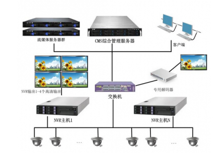
The packet-switched virtual matrix router implements the transmission and switching of image data through packet exchange (usually an IP packet). Packet-switching matrix has become more popular nowadays, such as the remote monitoring center that has been widely used, that is, the image is compressed at the local video end, and then the compressed bit stream is sent to the network (which can be a high-speed private network, internet, local area network, etc.). Remote, after decoding at the far end, is displayed on the big screen. The packet-switched digital matrix currently has two major limitations: large delays and poor image quality. Due to the transmission over the network, it will inevitably bring about delays. At the same time, in order to reduce the occupancy of the bandwidth, it is often necessary to compress the image at the sending end, and then perform decompression at the receiving end, after lossy compression of the image. It is difficult to ensure good image quality, while the encoding and decoding process will increase the delay. Therefore, the packet switching matrix cannot be applied to occasions with high requirements for real-time performance and image quality. More suitable for monitoring and use, illegal meeting the requirements of television and meetings.
Video Matrix Related Products:
Dispenser: A single signal is divided into multiple identical signals without signal loss and output to multiple display devices. Long-line drivers: Consolidate the ghosting and ghosting issues that occur with VGA signals over long distances. Selector: Select one of the multiple input signals to output to the display device. Switching Matrix: Select two or more than two signal sources for different display devices. In addition there are switches; scaler and so on. The matrix switcher can be independently used as an audio switching matrix, and can also be realized by using a dedicated cascade cable and VIDEO, VGA, and RGB matrix. The device has the power-off site protection function, can save the working state before the device is shut down, has an RS-232 communication interface for online use with the computer, and provides a communication protocol and a demonstration program to facilitate on-line use.
The development direction of the matrix system is multi-functional, large-capacity, networked, and remote switching. In general, the capacity of the matrix system reaches 64×16 which is a large capacity matrix. If a larger capacity matrix system is needed, it can also be achieved by cascading multiple matrix systems. The greater the capacity of the matrix, the higher the required technical level and the greater the difficulty of the design.
Category <br> <br> matrix of image signal with the development of technology, and improve the human visual audio and video; image signal transmission through the several stages of development, from AV Video to composite, component (YPbPr), then VGA signal, now to DVI and HDMI, DISPLAYPORT, etc.; In this process, due to the need to form a signal matrix switch, so that there is a corresponding matrix switcher in each signal phase; Now with IP technology and images The development of compression technology forms a virtual matrix switcher for multimedia streaming (based on MPEG-4, H2.64) exchange;
Divided into the form of transmission signal: analog matrix switcher and digital matrix switcher;
The analog matrix switcher is as follows:
The function of the matrix switcher is to transmit one or more video and audio signals to one or more display devices respectively, so we can classify the matrix switchers according to different signal sources. That is, the type of the matrix switcher is determined depending on the signal to be divided. The matrix switcher can be divided according to the type of signal source: VGA, AV, V, YPbPr matrix switcher and so on. For example: VGA matrix switcher is a matrix switcher with input and output signals of [] VGA signal. Other types can be analogized and will not be described here. The following will focus on the type of signal source.
VGA matrix:
VGA (Video Graphics Array), which is a display graphics array, is a computer display standard using analog signals proposed by IBM in 1987. VGA supports simultaneous display of 16 colors or 256 shades of gray at a higher resolution of 640X480 while simultaneously displaying 256 colors at a resolution of 320X240. VGA has quickly become popular because of its good performance. Vendors are expanding on the basis of VGA, such as increasing memory to 1M and enabling it to support higher resolutions such as 800X600 or 1024X768. These expansion modes are called VESA (Video Electronics). The Standards Association, the Video Electronics Standards Association's Super VGA mode, or SVGA for short, now supports SVGA mode for both video cards and monitors.
The composition of the VGA signal is divided into five types: RGBHV, which are the red, green, and blue primary colors and the line field sync signals. VGA transmission distance is very short. In order to transmit farther distances in the actual project, people disconnect the VGA cable, separate the RGBHV five kinds of signals and transfer them with five coaxial cables respectively. This transmission method is called RGB transmission. This signal is also called RGB signal. In fact, there is no difference between RGB and VGA.
VGA interface, also called D-Sub interface. The VGA interface is a D-type interface with a total of 15 pins empty, divided into three rows, five in each row. The VGA interface is the most widely used type of interface on the graphics card. Most graphics cards have such an interface. At present, most computers and external display devices are connected through an analog VGA interface. The computer internally generates digital display image information and is converted into R, G, and B primary color signals and lines by the digital/analog converters in the graphics card. Field synchronization signal, the signal is transmitted to the display device through the cable.
RGB matrix:
The composition of the VGA signal is divided into five types: RGBHV, which are the red, green, and blue primary colors and the line field sync signals. VGA transmission distance is very short. In order to transmit farther distances in the actual project, people disconnect the VGA cable, separate the RGBHV five kinds of signals and transfer them with five coaxial cables respectively. This transmission method is called RGB transmission. This signal is also called RGB signal, in fact, the signal is essentially no difference between RGB and VGA.
RGB transmission uses BNC plus coaxial cable transmission. The RGB cable has 5 connectors for receiving red, green, blue, horizontal sync and vertical sync signals. The BNC connector can insulate the video input signal, so that the interference between the signals is reduced and the signal bandwidth is larger than the normal D-SUB. The best signal response effect can be achieved.
AV matrix:
AV port (also called composite port) is a composite video connector, which is a common port used by home audio and video appliances to transmit analog video signals such as NTSC, PAL, and SECAM. The AV port is usually a yellow RCA port, with two red and white RCA ports transmitting the audio. European televisions usually use SCART ports instead of RCA ports. However, SCART is designed to carry better RGB signals than YUV, and it is also used to connect monitors, video games or DVD players. In professional applications, BNC ports are also used for better signal quality.
Transmitting in the AV port are the three source elements of the analog TV signal: Y, U, V, and the pulse signal as the synchronization reference. Y represents the brightness of the image (also known as brightness), and it contains sync pulses. As long as there is a Y signal, black and white TV images can be seen. Between the U signal and the V signal carries the color data, U and V are first mixed into two sets of orthogonal phases in a signal (the mixed signal is called chrominance), and then added to the Y signal. total. Since Y is the fundamental signal and UV is mixed with the carrier, this summation action is equivalent to division multiplexing.
The digital matrix switcher follows the DVI matrix:
DVI (Digital Visual Interface) interface, namely digital video interface. It is an interface launched by DDWG (Digital Display Working Group) formed by companies such as Silicon Image, Intel, Compaq, IBM, HP, NEC, and Fujitsu in 1999. standard.
The DVI interface is based on the technology of the PanalLink interface of Silicon Image, and is based on the TMDS (Transition Minimized Differential Signaling) electronic protocol as the basic electrical connection. TMDS is a differential signal mechanism that can encode pixel data and pass it through a serial connection. The digital signal generated by the video card is encoded by the transmitter in accordance with the TMDS protocol and sent to the receiver through the TMDS channel, which is then decoded and sent to the digital display device.
A DVI display system includes a transmitter and a receiver. The transmitter is the source of the signal, which can be built into the graphics chip, or it can appear on the graphics card PCB in the form of an additional chip; and the receiver is a circuit on the display, it can accept digital signals, decode it and pass it Through the digital display circuit, the signal from the video card becomes the image on the display.
The current DVI interface is divided into two types:
One is the DVI-D interface, which can only receive digital signals. There are only 3 rows and 8 columns with 24 pins on the interface. One of the pins in the upper right corner is empty. Not compatible with analog signals. The other is a DVI-I interface that is compatible with both analog and digital signals. Compatible with analog signals does not mean that the analog signal interface D-Sub interface can be connected to the DVI-I interface, but must use an adapter to use, usually the graphics card with this interface will have the relevant adapter.
DVI signal, HDCP signal and HDMI signal For VGA signals, the signal channels are essentially the same if they exclude various protocols, and they are all DVI signals. So first introduce the characteristics of DVI signal.
In the analog display mode, the digital RG.B signal (8-bit parallel signal) to be displayed is D/A-converted into an analog signal in the video card, transmitted to the display after being transmitted, and then processed to drive the RG.B electron gun and displayed on the fluorescent screen. The whole process is simulated. The digital display mode is different, the analog RGB signal reaches the display device (LCD or DLP, PDP, etc.) after A / D processing, converted to digital signals, and then by the digital signal in the TFT LCD sourcedriver through the DAC conversion into analog signal control The liquid crystal panel transmits or reflects light or the DMD chip reflects light or emits light from the plasma to achieve the display effect. In this process, there is obviously a conversion process from digital → analog → digital → analog. The signal loss is large (one A/D, D/A process will lose 6dB in frequency spectrum, and the maximum bandwidth is reserved as 1/1 of the pixel clock. 2), and there will be problems such as smearing, blurring, ghosting and other transmission problems. Currently, computer graphics cards with digital interfaces are quite common. Even notebook computers are equipped with DVI interfaces, and more and more devices in display devices have digital signal interfaces. Therefore, the digital-to-digital application environment has matured.
In DVI principle, the RGB digital signal to be displayed is combined with the HV signal, and each pixel is digitally encoded according to the minimum non-return-to-zero encoding method and the digital signal is converted into a series of RGB digital signals. Four signals, such as the code stream and the pixel clock, are transmitted in a balanced manner. The rate of each channel is 10 times the rate of the original pixel. For example, the resolution is 1024×768×70. The code stream clock is 70 MHz×10. It is equivalent to 0.7GHZ. The general DVI1.0 code stream is between 0.24GHZ and 1.65GHZ.
DVI has two standards, DVI1.0 and DVI2.0, of which DVI1.0 only uses one set of signal transmission channels, and the highest pixel clock for transmitting images is 165M (1600RGB*1200@60Hz, UXGA), the highest in the channel. The signal transmission stream is 1.65 GHz. DVI2.0 uses all two sets of signal transmission channels. The highest pixel clock for transmitting images is 330M, and the highest signal transmission rate in each set of channels is 1.65GHz. In the display device, there is no DVI2.0 application at present, so the DVI discussed in this article refers to the DVI1.0 standard.
HDMI Matrix:
HDMI (High-Definition Multimedia Interface), also known as High-Definition Multimedia Interface, is the first full-digital high-definition, multi-channel audio and intelligent format and control command data that supports uncompressed transmission over a single cable. Digital interface. The HDMI interface was initiated by Silicon Image Silicon Image and jointly developed by a working group jointly established by eight well-known consumer electronics manufacturers such as Sony, Hitachi, Panasonic, Philips, Thomson and Toshiba. HDMI's earliest interface specification, HDMI 1.0, was announced in December 2002. The current highest version is the HDMI 1.3 specification released in June this year.
HDMI is derived from the DVI interface technology. They are mainly based on the TMDS signal transmission technology of the American Crystal Corporation. This is the reason why the HDMI interface and the DVI interface can be converted to each other through adapters. The American Crystal Corporation is the only IC design and manufacturing company among the eight HDMI initiators. It is a leader in high-speed serial data transmission technology. Because the TMDS signal transmission technology mentioned below is developed by them, it is slightly here. Referring to TMDS (Transition Minimized Differential Signaling) is also known as minimizing differential signal transmission. It means that the original signal data is converted into 10 bits through XOR and XOR logic algorithms. The first 8 bits are calculated from the original signal. After obtaining, the ninth bit indicates the mode of operation, and the tenth bit is used to correspond to DC balance (DC-balanced, which means that the DC offset in the channel is guaranteed to be zero in the encoding process, and the level shifting achieves matching between different logical interfaces). The converted data is transmitted in differential transmission. This algorithm makes the overshoot and undershoot of the transition process of the transmitted signal decrease, and the transmitted data tends to be in DC balance, so that the electromagnetic interference of the signal to the transmission line is reduced, and the speed and reliability of the signal transmission are improved.
Under normal circumstances, HDMI connection consists of a pair of signal sources and receivers, and sometimes a system can also contain multiple HDMI input or output devices. Each HDMI signal input interface can receive the information of the connector according to the standard, and the same signal output interface also carries all the signal information. HDMI data line and receiver include three different TMDS data information channels and one clock channel. These channels support video, audio data, and additional information. Video, audio data, and additional information are transmitted to the receiver through three channels. The pixel clock is transmitted through the TMDS clock channel. After receiving the frequency parameter, the receiver restores the information transmitted from the other three data channels.
HDMI is pin compatible with DVI, but uses a different package. Compared with DVI, HDMI can transmit digital audio signals and add support for HDCP while providing better DDC optional features. HDMI supports data transmission rate of 5Gbps and can transmit up to 15 meters, enough to handle one 1080p video and one 8-channel audio signal. And because the demand for a 1080p video and an 8-channel audio signal is less than 4GB/s, there is still a lot of room for HDMI. This allows it to use one cable to connect the DVD player, receiver and PRR, respectively. In addition, HDMI supports EDID and DDC2B. Therefore, HDMI-equipped devices have the feature of “plug and playâ€, and the “negotiation†between the signal source and the display device is automatically performed, and the most suitable video/audio format is automatically selected. HDMI interface with HDCP protocol, to lay the foundation <br> <br> packet-switched virtual matrix is copyrighted to see high-definition film and television:
The packet-switched virtual matrix router implements the transmission and switching of image data through packet exchange (usually an IP packet). Packet-switching matrix has become more popular nowadays, such as the remote monitoring center that has been widely used, that is, the image is compressed at the local video end, and then the compressed bit stream is sent to the network (which can be a high-speed private network, internet, local area network, etc.). Remote, after decoding at the far end, is displayed on the big screen. The packet-switched digital matrix currently has two major limitations: large delays and poor image quality. Due to the transmission over the network, it will inevitably bring about delays. At the same time, in order to reduce the occupancy of the bandwidth, it is often necessary to compress the image at the sending end, and then perform decompression at the receiving end, after lossy compression of the image. It is difficult to ensure good image quality, while the encoding and decoding process will increase the delay. Therefore, the packet switching matrix cannot be applied to occasions with high requirements for real-time performance and image quality. More suitable for monitoring and use, illegal meeting the requirements of television and meetings.
Video Matrix Related Products:
Dispenser: A single signal is divided into multiple identical signals without signal loss and output to multiple display devices. Long-line drivers: Consolidate the ghosting and ghosting issues that occur with VGA signals over long distances. Selector: Select one of the multiple input signals to output to the display device. Switching Matrix: Select two or more than two signal sources for different display devices. In addition there are switches; scaler and so on. The matrix switcher can be independently used as an audio switching matrix, and can also be realized by using a dedicated cascade cable and VIDEO, VGA, and RGB matrix. The device has the power-off site protection function, can save the working state before the device is shut down, has an RS-232 communication interface for online use with the computer, and provides a communication protocol and a demonstration program to facilitate on-line use.
Fixed Ball,Hard Sealed Ball,Hard Sealed Sphere,Hard Sealed Fixed Ball
Antong Valve Co.,Ltd , https://www.atvalveball.com