Analysis of the working principle of USB+-C, the new favorite technology
2023-10-23 13:16:32
Since Apple released the new MacBook, the USB Type-C interface has become a hot topic. Let me analyze this USB Type-C from a hardware perspective so that everyone can better understand how USB Type-C works. Since Apple released the new MacBook, the USB Type-C interface has become a hot topic. Let me analyze this USB Type-C from a hardware perspective so that everyone can better understand how USB Type-C works.
Features
Small size, support for forward and reverse insertion, fast (10Gb). This small is for the USB interface on the previous computer, the actual relative to the microUSB on the android machine is still a little bigger:
USB Type-C: 8.3mmx2.5mm
microUSB: 7.4mmx2.35mm
Lightning: 7.5mmx2.5mm
Therefore, I can't see the advantages of USB Type-C on handheld devices in terms of size. And the speed can only see if the video transmission is needed.
Pin definition
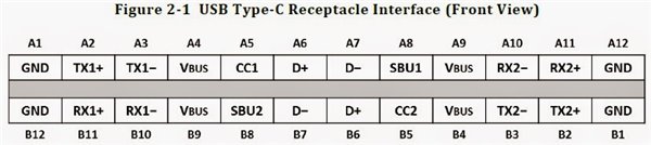
It can be seen that the data transmission mainly has two sets of differential signals of TX/RX, and CC1 and CC2 are two key pins, which have many functions:
• Detect connections, distinguish between front and back, distinguish between DFP and UFP, that is, master-slave • Configure Vbus, there are USB Type-C and USB Power Delivery modes • Configure Vconn, when there is a chip in the cable, a cc transmission signal , a cc becomes powered Vconn
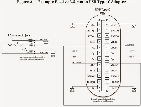
• Configure other modes, such as when connecting audio accessories, dp, pcie
There are 4 power and ground, which is why you can support up to 100W.
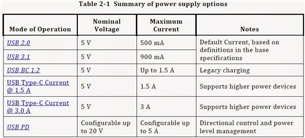
Don't look at the USB Type-C as if it can support up to 20V/5A. In fact, this requires a USB PD, and USB PD requires an additional pd chip, so don't assume that the USB Type-C interface can support 20V/5A.
Of course, there should be chips that are integrated together in the future.
The auxiliary signals sub1 and sub2 (Side band use) are used in certain transmission modes.
d+ and d- are standard before USB compatibility.
Here, USB3.0 has only one set of RX/TX, the speed is 5Gb, USB Type-C can use two sets to ensure the positive and negative, but in fact, only one set of RX/TX is used for data transmission. The speed has reached 10Gb. If you upgrade the protocol later, the two groups will be the same as DisplayPort 20Gb.
work process
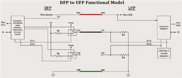
The DFP (Downstream Facing Port) is the master and the UFP (Upstream Facing Port) is the slave. In addition to DFP, UFP, and DRP (Dual Role port), DRP can be used as DFP or UFP. When DPR is connected to UFP, DRP is converted to DFP. When DRP is connected to DFP, DRP is converted to UFP. The two DRPs are connected together, at which point either one is DFP and the other is UFP.
The CC pin of the DFP has a pull-up resistor Rp, and the UFP has a pull-down resistor Rd. When not connected, DFP's VBUS is outputless. After the connection, the CC pin is connected, and the CC pin of the DFP detects the pull-down resistor Rd of the UFP, indicating that the connection is made, the DFP turns on the Vbus power switch, and the output power is supplied to the UFP. Which CC pin (CC1, CC2) detects the pull-down resistor determines the direction in which the interface is inserted, and switches RX/TX by the way.
The resistance Rd=5.1k, the resistance Rp is an indeterminate value. According to the previous figure, there are several power supply modes for the USB Type-C. What is the difference? The value of Rp is different. The value of Rp is different. CC pin detection The voltage is different, and then control which power mode is executed by the DFP.
It should be noted that the above picture shows two CCs. In fact, there is only one cc line in the cable without the chip.
The cable containing the chip is not two cc lines, but a cc, a Vconn, used to power the chip in the cable (3.3V or 5V). At this time, there is no pull-down resistor Rd on the cc end, but Pull-down resistor Ra, 800-1200 ohms.
When the CC pin is connected to both pull-down resistors
USB Type-C and DisplayPort, PCIE
USB PD is a BMC-encoded signal, and the previous USB is FSK, so there is incompatibility, and I don't know if there is any product that can be converted on the market.
The USB PD is transmitted on the CC pin. The PD has a VDM (Vendor defined message) function, which defines the device ID. When the device supports DP or PCIe, the DFP enters the alternate mode.
If DFP recognizes that the device is DP, it switches the MUX/Configuration Switch so that the Type-C USB3.1 signal pin changes to transmit the DP signal. AUX assistance is transmitted by SBU1, SUB2 of Type-C. HPD is a detection foot, similar to CC, so it is shared.
The DP has four sets of differential signals for lane0-3, and Type-C has four sets of differential signals for RX/TX1-2, so there is no problem with complete replacement. Moreover, in the alternative mode in the DP protocol, the USB signal and the DP signal can be simultaneously transmitted, the RX/TX1 transmits the USB data, and the RX/TX2 is replaced by the lane0, 1 two-group data transmission, which can be supported to 4k at this time.
If DFP recognizes that the device is DP, it switches the MUX/Configuration Switch to change the Type-C USB3.1 signal pin to transmit the PCIe signal. Similarly, PCIe uses RX/TX2 and SBU1, SUB2 to transmit data, and RX/TX1 transmits USB data.
The advantage of this is that one interface uses two devices at the same time. Of course, the conversion line can be done without any chips.
to sum up
USB Type-C has terminated the shortcomings of USB plug-in for a long time, saving people a lot of time, changing the direction for at least 2s, plugging and unplugging USB once a day for 1 billion people worldwide, 50% probability of inserting errors, total time consuming More than 277,000 hours, about 31 years, it is terrible.
One interface has three kinds of audio and video data, and the volume is still small. It can be foreseen that the Android machine can be changed to the USB Type-C interface in the future. If only USB2.0 is needed, only the cable needs to be redone, no chip, and the cost can be neglected.
As for Thunderbolt, lightning, what should it be? After all, it is a colorful world.
Http://Type-C-analysis.html
Http://news.chinawj.com.cn Editor: (Hardware Business Network Information Center) http://news.chinawj.com.cn
Features
Small size, support for forward and reverse insertion, fast (10Gb). This small is for the USB interface on the previous computer, the actual relative to the microUSB on the android machine is still a little bigger:
USB Type-C: 8.3mmx2.5mm
microUSB: 7.4mmx2.35mm
Lightning: 7.5mmx2.5mm
Therefore, I can't see the advantages of USB Type-C on handheld devices in terms of size. And the speed can only see if the video transmission is needed.
Pin definition
It can be seen that the data transmission mainly has two sets of differential signals of TX/RX, and CC1 and CC2 are two key pins, which have many functions:
• Detect connections, distinguish between front and back, distinguish between DFP and UFP, that is, master-slave • Configure Vbus, there are USB Type-C and USB Power Delivery modes • Configure Vconn, when there is a chip in the cable, a cc transmission signal , a cc becomes powered Vconn
• Configure other modes, such as when connecting audio accessories, dp, pcie
There are 4 power and ground, which is why you can support up to 100W.
Don't look at the USB Type-C as if it can support up to 20V/5A. In fact, this requires a USB PD, and USB PD requires an additional pd chip, so don't assume that the USB Type-C interface can support 20V/5A.
Of course, there should be chips that are integrated together in the future.
The auxiliary signals sub1 and sub2 (Side band use) are used in certain transmission modes.
d+ and d- are standard before USB compatibility.
Here, USB3.0 has only one set of RX/TX, the speed is 5Gb, USB Type-C can use two sets to ensure the positive and negative, but in fact, only one set of RX/TX is used for data transmission. The speed has reached 10Gb. If you upgrade the protocol later, the two groups will be the same as DisplayPort 20Gb.
work process
The DFP (Downstream Facing Port) is the master and the UFP (Upstream Facing Port) is the slave. In addition to DFP, UFP, and DRP (Dual Role port), DRP can be used as DFP or UFP. When DPR is connected to UFP, DRP is converted to DFP. When DRP is connected to DFP, DRP is converted to UFP. The two DRPs are connected together, at which point either one is DFP and the other is UFP.
The CC pin of the DFP has a pull-up resistor Rp, and the UFP has a pull-down resistor Rd. When not connected, DFP's VBUS is outputless. After the connection, the CC pin is connected, and the CC pin of the DFP detects the pull-down resistor Rd of the UFP, indicating that the connection is made, the DFP turns on the Vbus power switch, and the output power is supplied to the UFP. Which CC pin (CC1, CC2) detects the pull-down resistor determines the direction in which the interface is inserted, and switches RX/TX by the way.
The resistance Rd=5.1k, the resistance Rp is an indeterminate value. According to the previous figure, there are several power supply modes for the USB Type-C. What is the difference? The value of Rp is different. The value of Rp is different. CC pin detection The voltage is different, and then control which power mode is executed by the DFP.
It should be noted that the above picture shows two CCs. In fact, there is only one cc line in the cable without the chip.
The cable containing the chip is not two cc lines, but a cc, a Vconn, used to power the chip in the cable (3.3V or 5V). At this time, there is no pull-down resistor Rd on the cc end, but Pull-down resistor Ra, 800-1200 ohms.
When the CC pin is connected to both pull-down resistors
USB Type-C and DisplayPort, PCIE
USB PD is a BMC-encoded signal, and the previous USB is FSK, so there is incompatibility, and I don't know if there is any product that can be converted on the market.
The USB PD is transmitted on the CC pin. The PD has a VDM (Vendor defined message) function, which defines the device ID. When the device supports DP or PCIe, the DFP enters the alternate mode.
If DFP recognizes that the device is DP, it switches the MUX/Configuration Switch so that the Type-C USB3.1 signal pin changes to transmit the DP signal. AUX assistance is transmitted by SBU1, SUB2 of Type-C. HPD is a detection foot, similar to CC, so it is shared.
The DP has four sets of differential signals for lane0-3, and Type-C has four sets of differential signals for RX/TX1-2, so there is no problem with complete replacement. Moreover, in the alternative mode in the DP protocol, the USB signal and the DP signal can be simultaneously transmitted, the RX/TX1 transmits the USB data, and the RX/TX2 is replaced by the lane0, 1 two-group data transmission, which can be supported to 4k at this time.
If DFP recognizes that the device is DP, it switches the MUX/Configuration Switch to change the Type-C USB3.1 signal pin to transmit the PCIe signal. Similarly, PCIe uses RX/TX2 and SBU1, SUB2 to transmit data, and RX/TX1 transmits USB data.
The advantage of this is that one interface uses two devices at the same time. Of course, the conversion line can be done without any chips.
to sum up
USB Type-C has terminated the shortcomings of USB plug-in for a long time, saving people a lot of time, changing the direction for at least 2s, plugging and unplugging USB once a day for 1 billion people worldwide, 50% probability of inserting errors, total time consuming More than 277,000 hours, about 31 years, it is terrible.
One interface has three kinds of audio and video data, and the volume is still small. It can be foreseen that the Android machine can be changed to the USB Type-C interface in the future. If only USB2.0 is needed, only the cable needs to be redone, no chip, and the cost can be neglected.
As for Thunderbolt, lightning, what should it be? After all, it is a colorful world.
Http://Type-C-analysis.html
Http://news.chinawj.com.cn
Editor: (Hardware Business Network Information Center) http://news.chinawj.com.cn
PVC Coated Wire
PVC coated wire is material with an additional layer of polyvinyl chloride or polyethylene on the surface of the annealed wire, galvanized wire and other materials. The coating layer is firmly and uniformly attached to the metal wire to form the features of anti-aging, anti-corrosion, anti-cracking, long life and other characteristics.
Pvc Coated Wire,Pvc Coated Coiling Wire,Big Coil Pvc Coated Wire,Small Coil Pvc Coated Wire
HENGSHUI YUZHENG IMPORT AND EXPORT CO., LTD. , https://www.yzironnails.com